[0092] The preferred embodiments of the present invention will be described below with reference to the accompanying drawings. It should be understood that the preferred embodiments described herein are only used to illustrate and explain the present invention, but not to limit the present invention.
[0093] Usually, a visible image is a plane energy distribution map, which can be a radiation source of a luminous object itself, or the energy reflected or transmitted by the object after being irradiated by a light radiation source.
[0094] Digital images can be represented by two-dimensional discrete functions:
[0095] I=f(x, y)
[0096] Among them, (x, y) represents the coordinates of the image pixel, and the function value f(x, y) represents the gray value of the pixel at the coordinates.
[0097] It can also be represented by a two-dimensional matrix:
[0098] I=A(M, N)
[0099] Among them, A is the matrix representation, and M and N are the matrix row and column lengths.
[0100] When sampling an image, if there are M pixels in each row and N pixels in each column, the image size is M×N pixels, so A[M, N] constitutes an M×N real matrix. The matrix element a(m,n) represents the pixel value of the image in the mth row and the nth column, which is called a pixel or a pixel.
[0101] The information of each pixel in a grayscale image is described by a quantized grayscale level, with no color information. The gray level of a grayscale image pixel is usually 8 bits, that is, 0 to 255. "0" means pure black, "255" means pure white.
[0102] Images use numbers to arbitrarily describe pixels, intensities, and colors. The description information file has a large storage capacity, and the described object will lose details or produce aliasing during the zooming process. In terms of display, it is to distinguish the object at a certain resolution and then digitally present the color information of each point, which can be displayed directly and quickly on the screen. Resolution and grayscale are the main parameters that affect the display.
[0103] Under the requirement of certain fidelity, transform, encode and compress image data, remove redundant data and reduce the amount of data needed to represent digital images, so as to facilitate the storage and transmission of images. That is, the technology of representing the original pixel matrix in a lossy or lossless manner with a small amount of data is also called image coding.
[0104] Image compression coding can be divided into two categories: one type of compression is reversible, that is, the original image can be completely restored from the compressed data, and the information is not lost, which is called lossless compression coding; the other type of compression is irreversible, that is, from the compressed data. After the data can not completely restore the original image, there is a certain loss of information, which is called lossy compression coding.
[0105] In practical technology, the total amount of image data can be compressed in the following ways:
[0106] (1) Using luminance (Y) and chrominance (C) sampling methods;
[0107] (2) Divide the entire image into small regions for segmentation processing;
[0108] (3) Adopt inter-frame and intra-frame data compression technology.
[0109] JPEG is the abbreviation of Joint Photographic Experts Group (Joint Photographic Experts Group). The file suffix is named ".jpg" or ".jpeg". It is the most commonly used image file format. The lossy compression format can compress the image in a small storage space, and the repeated or unimportant data in the image will be lost, so it is easy to cause damage to the image data. In particular, using an excessively high compression ratio will significantly reduce the quality of the image recovered after final decompression. If high-quality images are pursued, it is not appropriate to use an excessively high compression ratio. However, JPEG compression technology is very advanced. It uses lossy compression to remove redundant image data. It can display very rich and vivid images while obtaining a very high compression rate, that is, it can obtain better image quality with the least disk space. . Moreover, JPEG is a very flexible format, with the function of adjusting image quality, allowing files to be compressed with different compression ratios, and supporting multiple compression levels. The compression ratio is usually between 10:1 and 40:1. The larger the ratio, the lower the quality; conversely, the lower the compression ratio, the better the quality. For example, a 1.37Mb BMP bitmap file can be compressed to 20.3KB. A balance can also be found between image quality and file size. JPEG format mainly compresses high-frequency information, and retains color information better. It is suitable for use in the Internet and can reduce the transmission time of images. It can support 24bit true color, and is also widely used in images that require continuous tone. After many comparisons, the use of level 8 compression is the best ratio for both storage space and image quality.
[0110] Enhancing useful information in an image, which can be a distortion process, is intended to improve the visual effect of an image for a given image's application. Purposefully emphasize the overall or local characteristics of the image, make the original unclear image clear or emphasize some interesting features, expand the difference between the features of different objects in the image, suppress the uninteresting features, and improve the image. Quality, rich information, strengthen image interpretation and recognition effect, to meet the needs of some special analysis.
[0111] The method of image enhancement is to add some information or transform data to the original image by certain means, selectively highlight the interesting features in the image or suppress some unwanted features in the image, so that the image matches the visual response characteristics. In the process of image enhancement, the reason for image degradation is not analyzed, and the processed image is not necessarily close to the original image. Image enhancement technology can be divided into two categories: spatial domain-based algorithms and frequency domain-based algorithms according to the different spaces in which the enhancement process is performed.
[0112] The air domain method is to operate on the pixels in the image, which is described by the formula as follows:
[0113]g(x,y)=f(x,y)×h(x,y)
[0114] where f(x, y) is the original image; h(x, y) is the space conversion function; g(x, y) represents the processed image.
[0115] The algorithm based on the space domain directly operates on the gray level of the image, while the algorithm based on the frequency domain modifies the transform coefficient value of the image in a certain transform domain of the image, which is an indirect enhancement algorithm. Algorithms based on space domain are divided into point operation algorithm and neighborhood denoising algorithm. The point operation algorithm is gray level correction, gray transformation and histogram correction, etc., the purpose is to make the image imaging uniform, or to expand the dynamic range of the image and expand the contrast. Neighborhood enhancement algorithms are divided into two types: image smoothing and sharpening.
[0116] Infrared images generally contain noise due to some interference. Noise blurs the image and even drowns out the features. If the noise is not processed in time, it will affect the subsequent processing process and even the output results, and may even get wrong conclusions. Therefore, image noise filtering becomes an important part of infrared image preprocessing. Smoothing filtering in the spatial or frequency domain can suppress image noise and improve the signal-to-noise ratio of the image.
[0117] When the neighborhood average method is used, the large template requires a large amount of computation, takes a long time, and has a heavy degree of blurring, resulting in poor image quality after processing. Moreover, as the template becomes larger, the amount of computation increases rapidly, the time-consuming increases, the degree of blurring becomes heavier, and the image effect is poor. Therefore, if you use this method to process images, it is best to use a smaller template. When the median filter method is used, the large window requires a large amount of computation and takes a long time, but the image effect after processing is basically the same as when using a small window. Moreover, as the window becomes larger, the amount of computation is larger and the time-consuming is longer, but the image effect is not significantly improved. Therefore, if this method is used to process images, it is better to use a smaller window and use a fast algorithm. It can be seen from the processed images that the filtering effect of the neighborhood average method is poor, the noise reduction is not obvious, and the blur of the image is increased. The image effect after median filtering is good, the image outline is clear, and the noise is greatly reduced, which makes subsequent target recognition and tracking more convenient. The median filter not only eliminates the influence of strong impulse noise, but also preserves the edge of the image. The filtering effect of the gradient reciprocal smoothing algorithm is good, but the operation time is too long, and the effect is very good when the real-time requirement is not high. In view of the many advantages of median filtering, and the fact that median filtering is easy to implement in hardware, it can meet the requirements of real-time performance.
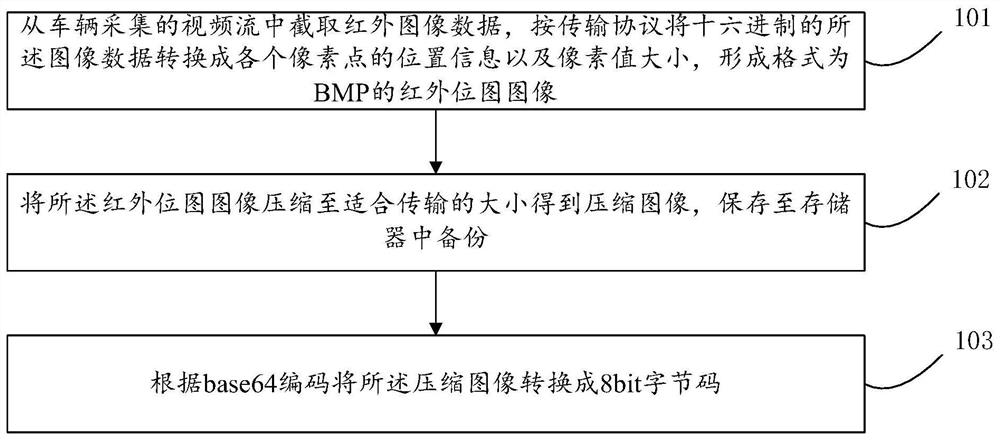
[0118] figure 1 This is a flow chart of the compression and enhancement of the infrared image of the vehicle in the embodiment of the present invention. like figure 1 As shown, the compression and enhancement process of the infrared image of the vehicle includes the following steps:
[0119] Step 101: Intercept infrared image data from the video stream collected by the vehicle, convert the hexadecimal image data into the position information and pixel value size of each pixel point according to the transmission protocol, and form an infrared bitmap image in the format of BMP. .
[0120] In the embodiment of the present invention, based on an infrared image transmission system, the transmitting end is composed of an infrared camera module, a collection module, a compression module, a memory, a transmitting station and an omnidirectional antenna; the receiving end is composed of an omnidirectional antenna, a receiving station, a restoration It is composed of module, enhanced module, memory and upper computer display. like figure 2 As shown, it is a block diagram of the hardware structure of the transmitter. based on figure 2 In the system shown, the embodiment of the present invention realizes the compression and enhancement processing of infrared images.
[0121] The invention designs a vehicle infrared image compression and enhancement system, which utilizes the principle of infrared imaging and image compression and enhancement to solve the problems of low precision, low speed and large image occupied space of the visual sensor in the Internet of Vehicles. The embodiment of the present invention is mainly the transmitting end of the infrared image transmission system. Among them, the transmitter consists of an infrared camera module, a collection module, a compression module, a memory, a transmitter radio and an omnidirectional antenna; the receiver consists of an omnidirectional antenna, a receiver radio, a recovery module, an enhancement module, a memory, and a host computer display.
[0122] The main work flow of the transmitter of the vehicle infrared image compression and enhancement system designed by the present invention is as follows: the system intercepts the infrared image data from the video stream sent by the infrared camera to the data processor through the acquisition module, and converts the hexadecimal data into hexadecimal according to the transmission protocol. The image data is converted into the position information and pixel value size of each pixel point to form an infrared bitmap image in the format of BMP, and then the compression module compresses the image to a size suitable for transmission, saves it to the memory for backup, and finally encodes it with base64. The compressed image is converted into 8bit byte code and transmitted to the air by the transmitting station through the omnidirectional antenna, and transmitted to the receiving station;
[0123] The infrared camera module uses an uncooled focal plane micro-thermal DM20 network temperature measurement module, which is divided into two parts, the front part is responsible for shooting and obtaining infrared images, and is organized and packaged into several hexadecimals by the built-in chip. The data packets are output from the SPI_MISO pin on the chip in the form of SPI signals and sent to the second half of the infrared detector; the second half is responsible for transmitting several received data packets from the RJ45 interface to the data processor through the network cable. .
[0124] The acquisition module can use any host computer capable of running C++ programs, such as a PC, a Raspberry Pi, and a single-chip microcomputer. The present invention uses a computer whose system is Windows 10. The infrared detector and the computer are connected by a network cable, and the interface is a network port, namely RJ45. Both the infrared detector and the computer have their own power adapters for stable power supply.
[0125] The described image transmission module adopts Nissei ND series 19.2Kbps high-speed data transmission radio, equipped with MD192 intelligent modem, adopts digital signal processing DSP technology, and realizes wireless digital modulation and demodulation algorithm in real time by software, which can be used by AT command. The software sets various parameters;
[0126] The compression module uses the JPEG image compression algorithm, and the compression ratio adopted is 10:1.
[0127] The described memory uses a 16g flash memory chip.
[0128] Step 102: Compress the infrared bitmap image to a size suitable for transmission to obtain a compressed image, and save it to a memory for backup.
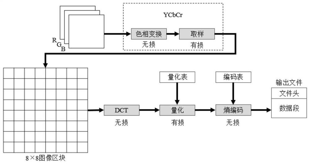
[0129] like image 3 As shown, it is a flowchart of a JPEG encoder provided by an embodiment of the present invention. The YCbCr color space used by JPEG supports 1 to 4 color components, and the BMP is the RGB color space. To compress a BMP image, first convert the color space. RGB, YUV, YCbCr, etc. have 3 color components; Magenta, Cyan, Yellow, and Black (Magenta, Cyan, Yellow, and Black) have 4 color components. The computer display image adopts the RGB color model, and the image data is formed by adding three components of R, G, and B. In this example, the YCbCr color space is used, and the color space conversion from RGB to YCbCr needs to be performed. The conversion relationship between RGB and YCrCb is as follows:
[0130] Y=0.299000R+0.587000G+0.114000B
[0131] Cb=-0.169736R-0.331264G+0.500002B
[0132] Cr=0.500000R-0.418688G-0.081312B
[0133] Among them, Y is the luminance component, Cb(U) and Cr(V) are the blue-red intensity components, and R, G, and B are the colors of the red, green, and blue channels, respectively.
[0134] Image pixels are stored in unsigned integers. In an image, these sampled data must be converted to two's complement representation before any transformations or mathematical calculations are performed. The DC level offset is to ensure that the sampling of the input data information is approximately centered around the dynamic range of zero. The method is: Assuming the sampling precision of the image components is n, each pixel value in the component should be subtracted by 2 n-1.
[0135] In general, the human eye is more sensitive to changes in brightness than color changes, so the Y component is more important than the Cb and Cr components. After the color space conversion, the information of the image is mainly contained in the luminance component Y. A large amount of redundant color information is stored in the chrominance components Cb and Cr. Therefore, subsampling can be used to reduce the amount of chroma data and lose a small amount of information to achieve image compression. In the JPEG image standard, the sub-sampling format usually adopted is 4:1:1 or 4:2:2.
[0136] DCT (Discrete Fourier Transform, discrete cosine transform) is processed based on 8×8 sub-blocks. Therefore, it is necessary to divide the original image data into blocks before transforming. Each pixel in the original image has 3 components that appear alternately, and these 3 components need to be separated and stored in 3 tables.
[0137] DCT transform is a commonly used transform coding method in code rate compression. It uses orthogonal transform to remove spatial redundant information and realize compression coding. First, the source image data is divided into N×N pixel blocks, and then DCT is used to perform transformation operations on each pixel block one by one. Usually, the energy of the image is concentrated in the low-frequency region after discrete cosine transformation, so DCT is mainly used to remove the spatial redundancy of image data. After DCT, the correlation between the coefficients of the image data will decrease, and most of the energy of the image data will be concentrated in a few DCT coefficients. DCT can effectively remove the correlation between image data and concentrate signal energy. It is the core algorithm of JPEG standard data compression, and is very important in image compression applications. DCT is evolved from the Fourier transform.
[0138] The forward transform formula of one-dimensional discrete cosine transform is:
[0139]
[0140] Among them, n, k=0, ..., N-1, N is the length of the image sequence before compression, and x(n) is the image sequence before compression.
[0141] The positive transformation formula of two-dimensional DCT is (N generally takes 8):
[0142]
[0143] Among them, F(u, v) is the transformed image, f(x, y) is the original image, and C(u) and C(v) are the blue-red intensity components.
[0144] The inverse transformation formula of 2D DCT is:
[0145]
[0146] Among them, F(u, v) is the transformed image, f(x, y) is the original image, and C(u) and C(v) are the blue-red intensity components.
[0147] The coefficients of the above formulas are: x, y, u, v=0, 1, ......, N-1
[0148]
[0149] Among them, C(u) and C(v) are the blue-red intensity components.
[0150] After the image data is converted into DCT coefficients, a quantization stage is required before encoding can be performed. After the 8×8 image data is transformed by DCT, its high-frequency and low-frequency energy are concentrated in the lower right corner and upper left corner, respectively, as shown in Table 1 and Table 2.
[0151] Table 1 Standard luminance quantization table
[0152] 16 11 10 16 24 40 51 61 12 12 14 19 26 58 60 55 14 13 16 24 40 57 69 56 14 17 22 29 51 87 80 62 18 22 37 56 68 109 103 77 24 35 55 64 81 104 113 92 49 64 78 87 103 121 120 101 72 92 95 98 112 100 103 99
[0153] Table 2 Standard colorimetric quantification table
[0154] 17 18 24 47 99 99 99 99 18 21 26 66 99 99 99 99 24 26 56 99 99 99 99 99 47 66 99 99 99 99 99 99 99 99 99 99 99 99 99 99 99 99 99 99 99 99 99 99 99 99 99 99 99 99 99 99 99 99 99 99 99 99 99 99
[0155] From the perspective of the spatial domain, take the upper left corner and go to the lower right corner, the realized function is similar to a low-pass filter. After quantization, the accuracy of the DCT coefficients will be reduced, the AC coefficients that have a relatively low role in the image data will be reduced, and the amount of image data will be reduced (the AC coefficients represent image details), thus achieving the purpose of image compression. Therefore, in general, quantization is the most important step in image compression, and the main reason for image quality degradation is quantization. Quantization requires two frequency coefficients, which deal with luminance and chrominance respectively. Each DCT coefficient is used to divide the quantization coefficient value obtained by the respective quantization matrix and then rounded (usually rounded) to complete quantization. Uniform quantization is used in JPEG. It can be seen from the quantization table that the value in the lower right corner is larger and the value in the upper left corner is smaller. Through this step, the goal of retaining low-frequency components and controlling high-frequency components can be achieved.
[0156] Usually, using different quantization tables, the image compression effect achieved is different. As shown in Table 1 and Table 2, it is a reference standard proposed by the JPEG standard. When using, users can also adjust it according to the characteristics of the source image and the performance of the image display. It can be found from the standard quantization table that the two tables have different quantization and step sizes, which are finer for luminance and coarser for chrominance. This is because the colors used by the image are in YUV format. Relatively speaking, the value of the chrominance (Y) component is more important. We can separately implement fine quantization for the luminance component (Y) and coarse quantization for the chrominance component (UV), which ensures a higher compression ratio.
[0157] The JPEG standard stipulates that the coefficient values of 64 DCTs are stored at a time in the order shown in the figure below. The advantage of this is that adjacent points in such a sequence are also adjacent in the image. The specific process is as Figure 4 shown.
[0158] In the JPEG standard, the coding method adopted for the DC coefficients is DPCM (Difference Pulse Code Modulation). The DC coefficient has two characteristics, one is that the coefficient value is relatively high; the other is that the coefficient values of two adjacent 8×8 image blocks do not change much. Coefficient difference: Diff=DC i -DC i-1 , which encodes the difference. The advantage of this is that the difference is encoded in fewer bits than the original.
[0159] The other values in the 8x8 image block are AC coefficients, using run-length coding (RLC). There are many values of 0 in the quantized AC coefficients, and the use of run-length coding can effectively reduce the size of the data. The codeword of run-length encoding is described by two Bytes, such as Figure 5 shown.
[0160] Step 103: Convert the compressed image into 8-bit bytecode according to base64 encoding.
[0161] In order to realize the above process, the technical solution of the present invention also provides a compression and enhancement system for vehicle infrared images, such as Image 6 As shown, the compression and enhancement system of the infrared image of the vehicle includes an infrared camera module 21, a collection module 22, a compression module 23, a memory 24, a transmitting station 25 and an omnidirectional antenna 26, wherein:
[0162] The infrared camera module 21 is used to collect video stream data;
[0163] The acquisition module 22 is used to intercept the infrared image data from the video stream collected by the infrared camera module, and convert the hexadecimal image data into the position information and pixel value size of each pixel point according to the transmission protocol to form a format. Infrared bitmap image for BMP;
[0164] The compression module 23 is used to compress the image to a compressed image of a size suitable for transmission, and save it to the memory for backup;
[0165] the memory 24, for saving and backing up the compressed image;
[0166] The transmitting station 25 is used to convert the compressed image into 8bit byte code according to base64 encoding and send it to the omnidirectional antenna;
[0167] The omnidirectional antenna 26 is used for transmitting the compressed image.
[0168] The compression module 23 specifically includes:
[0169] A space change unit, for carrying out YCbCr color space transformation to the RGB color of the infrared bitmap image of the BMP, to obtain a JPEG image;
[0170] A DC translation unit, configured to perform DC level shift on the JPEG image;
[0171] a subsampling unit, configured to perform subsampling on the YCbCr component of the JPEG image; the sampling ratio of the YCbCr component is 4:1:1 or 4:2:2;
[0172] a block unit, configured to divide the sub-sampled JPEG image into N×N sub-blocks according to pixel points;
[0173] The DCT transform unit is used to perform discrete Fourier DCT transform on the N×N sub-blocks obtained by dividing the JPEG image into blocks, and convert the image data into corresponding DCT coefficients;
[0174] a quantization unit, configured to quantize and compress the DCT coefficients;
[0175] Zig-zag scanning unit for performing Zig-zag scanning on the quantized and encoded data;
[0176] an encoding unit for separately encoding the alternating current AC coefficients and the direct current DC coefficients on the data after the Zig-zag scanning;
[0177] A run-length code encoding unit, configured to perform run-length RLC encoding on the AC coefficients.
[0178] In the space change unit, the RGB color of the infrared bitmap image of the BMP is transformed into the YCbCr color space, and is carried out according to the following formula:
[0179] Y=0.299000R+0.587000G+0.114000B
[0180] Cb=-0.169736R-0.331264G+0.500002B
[0181] Cr=0.500000R-0.418688G-0.081312B
[0182] Among them, Y is the luminance component, Cb(U) and Cr(V) are the blue-red intensity components, and R, G, and B are the colors of the red, green, and blue channels, respectively.
[0183] The discrete Fourier DCT transform in the DCT transform unit is performed in the following manner:
[0184] The positive transformation formula of the one-dimensional DCT transform is:
[0185]
[0186] Among them, n, k=0, ......, N-1, N is the length of the image sequence before compression, x(n) is the image sequence before compression;
[0187] The forward transformation formula of two-dimensional DCT is:
[0188]
[0189] Among them, F(u, v) is the transformed image, f(x, y) is the original image, and C(u) and C(v) are the blue-red intensity components;
[0190] The inverse transformation formula of 2D DCT is:
[0191]
[0192] Among them, F(u, v) is the transformed image, f(x, y) is the original image, and C(u) and C(v) are the blue-red intensity components;
[0193] The coefficients of the above formulas are: x, y, u, v=0, 1, ......, N-1
[0194]
[0195] Among them, C(u) and C(v) are the blue-red intensity components.
[0196] To sum up, the technical scheme of the present invention proposes a compression and enhancement scheme for infrared images of vehicles. The infrared image data is intercepted from the video stream collected by the vehicle, and the image data in hexadecimal is converted according to the transmission protocol. into the position information and pixel value size of each pixel point to form an infrared bitmap image with a format of BMP; compress the infrared bitmap image to a size suitable for transmission to obtain a compressed image, and save it to the memory for backup; Convert the compressed image into 8bit bytecode. Using the principles of infrared imaging and image compression and enhancement, the problems of low precision, low speed and large image space of vision sensors in the Internet of Vehicles are solved. The invention also has the advantages that the compression rate is high, and the bandwidth requirement of the communication channel is low; the transmission rate is fast, and the processing rate of the data processing center is improved;
[0197] As will be appreciated by one skilled in the art, embodiments of the present invention may be provided as a method, system, or computer program product. Accordingly, the present invention may take the form of an entirely hardware embodiment, an entirely software embodiment, or an embodiment combining software and hardware aspects. Furthermore, the present invention may take the form of a computer program product embodied on one or more computer-usable storage media having computer-usable program code embodied therein, including but not limited to disk storage, optical storage, and the like.
[0198] The present invention is described with reference to flowchart illustrations and/or block diagrams of methods, apparatus (systems), and computer program products according to embodiments of the invention. It will be understood that each flow and/or block in the flowchart illustrations and/or block diagrams, and combinations of flows and/or blocks in the flowchart illustrations and/or block diagrams, can be implemented by computer program instructions. These computer program instructions may be provided to the processor of a general purpose computer, special purpose computer, embedded processor or other programmable data processing device to produce a machine such that the instructions executed by the processor of the computer or other programmable data processing device produce in the process of realization Figure 1 process or processes and/or blocks Figure 1 A means for the functions specified in a block or blocks.
[0199] These computer program instructions may also be stored in a computer-readable memory capable of directing a computer or other programmable data processing apparatus to function in a particular manner, such that the instructions stored in the computer-readable memory result in an article of manufacture comprising instruction means, the instructions The device is implemented in the process Figure 1 process or processes and/or blocks Figure 1 the function specified in a box or boxes.
[0200] These computer program instructions can also be loaded on a computer or other programmable data processing device to cause a series of operational steps to be performed on the computer or other programmable device to produce a computer-implemented process such that Instructions are provided for implementing the process in Figure 1 process or processes and/or blocks Figure 1 The steps of the function specified in the box or boxes.
[0201] It will be apparent to those skilled in the art that various modifications and variations can be made in the present invention without departing from the spirit and scope of the invention. Thus, provided that these modifications and variations of the present invention fall within the scope of the claims of the present invention and their equivalents, the present invention is also intended to include these modifications and variations.