Receiver apparatus and intra-subject information acquiring system

A technology of a receiving device and an object to be inspected, which is applied to closed-circuit television systems, in-vivo radio detectors, components of television systems, etc. The effect of preventing capacity

Active Publication Date: 2008-09-03
OLYMPUS CORP
View PDF1 Cites 2 Cited by
  • Summary
  • Abstract
  • Description
  • Claims
  • Application Information

AI Technical Summary

Problems solved by technology

At this time, since the receiving device does not synchronize the frequency of the wireless signal transmitted from the capsule endoscope with the frequency of the r

Method used


Image

  • Receiver apparatus and intra-subject information acquiring system
  • Receiver apparatus and intra-subject information acquiring system
  • Receiver apparatus and intra-subject information acquiring system

Examples


Example Embodiment

[0044] (Embodiment 1)

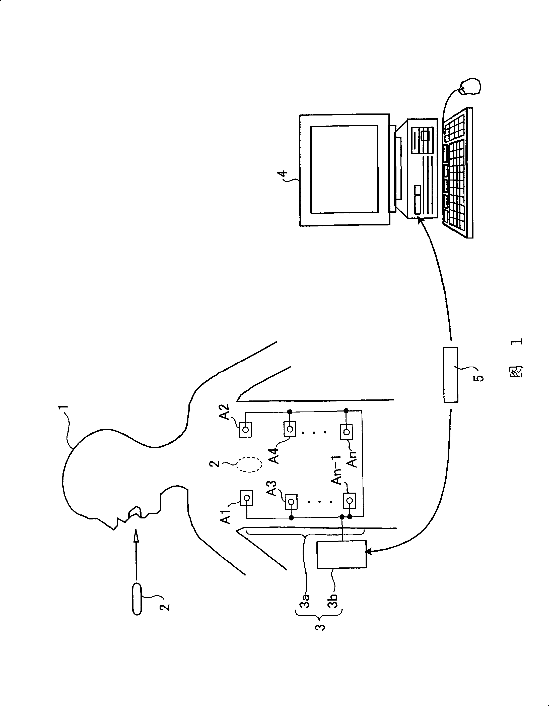
[0045] FIG. 1 is a schematic diagram showing the overall configuration of a wireless in-subject information acquisition system including a receiving device according to the first embodiment. In FIG. 1, the in-subject information acquisition system includes: a capsule endoscope 2 that is introduced into the body of the subject 1 to capture images of the body cavity and transmit data such as image signals to a receiving device 3; and a receiving device 3 , It has wireless receiving function. In addition, the in-subject information acquisition system includes: a display device 4 that displays an image in a body cavity based on a wireless signal received by the receiving device 3; and a portable recording medium 5 that is used to perform the communication between the receiving device 3 and the display device 4. data transmission. The receiving device 3 includes an antenna group 3a and an external device 3b that performs processing and the like of the wireless s...

Example Embodiment

[0091] (Embodiment 2)

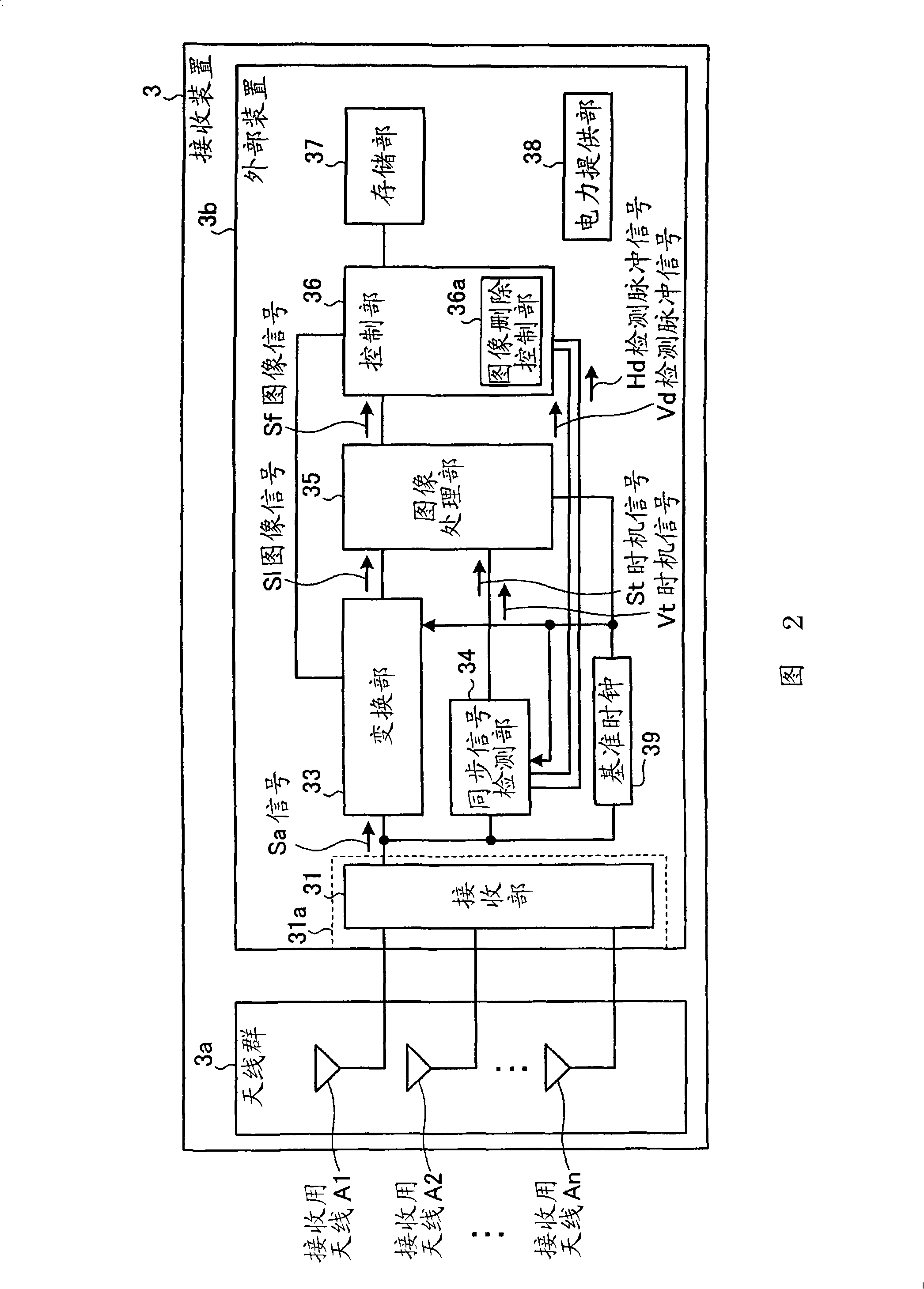
[0092] Next, Embodiment 2 will be described. FIG. 13 is a schematic block diagram showing the overall configuration of the receiving device 203 according to the second embodiment. The receiving device 203 shown in FIG. 13 is different from the receiving device 3 shown in FIG. 2 in the structure of the image deletion control unit 36a and the image deletion control unit 336a. The other structure is the same as that of the receiving device 3, and the same structure is added Same reference number.

[0093] Here, refer to Figure 14 The illustrated flowchart explains the image deletion control processing procedure of the image deletion control unit 336a according to the second embodiment. First, the image deletion control unit 336a acquires the detection pulse signal Hd of the horizontal synchronization signal (step S302). Then, the image deletion control unit 336a determines whether the horizontal synchronization signal detection unit 236 can detect a predeterm...

Example Embodiment

[0096](Embodiment 3)

[0097] Next, Embodiment 3 will be described. FIG. 15 is a schematic block diagram showing the overall configuration of the receiving device 303 according to the third embodiment. The receiving device 303 shown in FIG. 15 is different from the receiving device 3 shown in FIG. 2 in the structure of the image deletion control unit 36a and the image deletion control unit 436a. The other structure is the same as that of the receiving device 3. Reference sign.

[0098] Here, refer to Figure 16 The shown flowchart explains the image deletion control processing procedure of the image deletion control unit 436a. First, the image deletion control unit 436a acquires the detection pulse signal Hd of the horizontal synchronization signal (step S402). After that, the image deletion control unit 436a determines whether the horizontal synchronization signal detection unit 236 can detect a predetermined number or more of horizontal synchronization signals for one frame base...


PUM


Abstract

The present invention acquires much accurate image information having no noise, without increasing load in the post-processing of the image information, a receiving apparatus 3 includes: a synchronization signal detector 34 that detects a horizontal synchronization signal and a vertical synchronization signal; an image processor 35 that performs an image generation process of each frame based on the horizontal synchronization signal and the vertical synchronization signal detected by the synchronization signal detector 34; and an image deletion controller 36a that controls to delete an image of the current frame, when a horizontal synchronization signal within one frame detected by the synchronization signal detector 34 is not continuously detected by a first predetermined number or more, or when a horizontal synchronization signal within one frame detected by the synchronization signal detector 34 is not detected by a second predetermined number or more, or when a vertical synchronization signal detected by the synchronization signal detector 34 is not continuously detected by a third predetermined number or more.

Description

technical field [0001] The present invention relates to a receiving device and a system for obtaining information in a subject, and more particularly to a receiving device for processing a wireless signal including an information component transmitted from a transmitting device, and a subject including the receiving device and a device introduced into a subject. In vivo information acquisition system. Background technique [0002] In recent years, in the field of endoscopes, a capsule-type endoscope equipped with an imaging function and a wireless communication function has appeared. The capsule endoscope has a function of swallowing the capsule endoscope from the mouth of a subject who is a subject for observation (examination), until the subject's biological body naturally During the observation period up to discharge, the capsule endoscope moves in accordance with the peristaltic motion inside (inside the body cavity) of organs such as the stomach and small intestine, an...

Claims


Application Information

Patent Timeline
IPC IPC(8): A61B1/00A61B1/04A61B5/07H04N5/08H04N7/18
CPCA61B1/00016A61B1/041A61B1/273H04N5/10H04N7/18
Inventor 重盛敏明永濑绫子
Owner OLYMPUS CORP
Why Eureka
Try Eureka