Light source device for exposure, exposure device, and exposure method

A light source device, the technology of the optical axis direction, which is applied to the photoplate process exposure device, microlithography exposure equipment, optics and other directions, can solve the problem of narrow wavelength band, etc., and achieve the effect of improving the efficiency of exposure work

Inactive Publication Date: 2021-10-22
V TECH CO LTD
View PDF3 Cites 0 Cited by
  • Summary
  • Abstract
  • Description
  • Claims
  • Application Information

AI Technical Summary

Problems solved by technology

[0003] Here, when a conventional resist matching the wavelength band of a mercury lamp is used as it is, the single-wavelength LED element has a narrower wavelength band than that of a mercury lamp.

Method used


Image

  • Light source device for exposure, exposure device, and exposure method
  • Light source device for exposure, exposure device, and exposure method
  • Light source device for exposure, exposure device, and exposure method

Examples


no. 1 approach

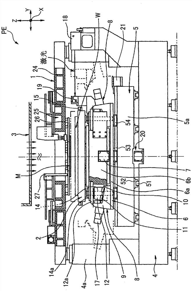
[0099] Hereinafter, a first embodiment of the exposure apparatus according to the present invention will be described in detail based on the drawings. Such as figure 1 As shown, the proximity exposure apparatus PE uses a mask M smaller than a workpiece W as a material to be exposed, holds the mask M by a mask stage (mask support portion) 1 , and uses a workpiece stage (work support portion) 2 The workpiece W is held, and the mask M is placed close to the workpiece W to face each other with a predetermined exposure gap, and the pattern exposure light of the mask M is irradiated from the illumination device 3 to thereby expose the pattern of the mask M. Transfer to the workpiece W. In addition, the workpiece stage 2 is moved stepwise in two axial directions, the X-axis direction and the Y-axis direction, with respect to the mask M, and exposure transfer is performed every step.

[0100] In order to move the workpiece stage 2 stepwise in the X-axis direction, an X-axis stage fe...

no. 2 approach

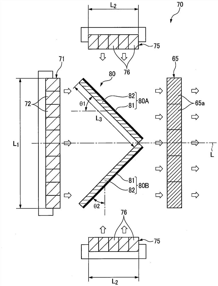
[0144] Next, refer to Image 6 The light source device 70 of the second embodiment will be described. Such as Image 6 As shown, in the light source device 70 of this embodiment, both ends 83 of the two dichroic mirrors 80A and 80B are cut parallel to the optical axis direction L from the dichroic mirror 80 toward the fly-eye lens 65 . As a result, the dichroic films 81 of the two dichroic mirrors 80A and 80B are in contact with each other at the top of the V shape, so the dichroic mirrors 80A and 80B make the light irradiated from the first LED array 71 within the width of the dichroic mirror 80 . In the direction (the direction perpendicular to the optical axis direction L), the entire area is uniformly transmitted, and the light irradiated from the second LED array 75 can be reflected in a wide range, thereby improving the efficiency.

[0145] Moreover, in this case, the 1st LED array 71 and the 2nd LED array 75 can also be arrange|positioned by switching the position wit...

no. 3 approach

[0148] Next, refer to Figure 7 The light source device 70 of the third embodiment will be described. Such as Figure 7 As shown, the present embodiment uses two dichroic mirror fixing frames 85 , and the method of fixing the two dichroic mirrors 80A and 80B described in the above embodiment will be described.

[0149] The dichroic mirror fixing frame 85 has the following shape: the three frames 85a, 85b, and 85c covering three of the four sides of the rectangular dichroic mirrors 80A, 80B are combined into a substantially "U" shape, and the dichroic mirrors The side surfaces of the mirrors 80A and 80B facing each other are open. Furthermore, one side surface of the dichroic mirrors 80A and 80B fits into the groove 86 formed in the frame body 85a of the substantially U-shaped dichroic mirror fixing frame 85, and the upper surfaces of the dichroic mirrors 80A and 80B are held in place by the buffer member 88. The pressing screw 87 provided on the frame body 85c presses towar...


PUM

PropertyMeasurementUnit
wavelengthaaaaaaaaaa
reflectanceaaaaaaaaaa

Abstract

The present invention provides a light source device for exposure that is able to synthesize light from a plurality of LED elements having different peak wavelengths, and is compactly configured, an exposure device using the light source device, and an exposure method. This light source device for exposure is provided with: a first LED array (71) having a plurality of first LED elements (72) that emit light of a first peak wavelength; a second LED array (75) having a plurality of second LED elements (76) that emit light of a second peak wavelength different from the first peak wavelength; a photosynthetic element (80) that is provided with two dichroic films (81) for transmitting light in a specific wavelength band and reflecting light in the other wavelength bands, and synthesizes light from the first and second LED arrays (71, 75); and a fly-eye lens (65) on which the light synthesized by the photosynthetic element (80) is incident.

Description

technical field [0001] The present invention relates to a light source device, an exposure device, and an exposure method for exposure, and more specifically, to a light source device, an exposure device, and an exposure method for exposure that use light irradiated from an LED element as a light source. Background technique [0002] Conventionally, mercury lamps have been used as UV light sources in exposure apparatuses used for lithography of flat panel displays, printed circuit boards, semiconductor elements, and the like. However, in recent years, restrictions on the use of mercury have become severe, and LED conversion of UV light sources has been demanded. [0003] Here, when a conventional resist matching the wavelength band of a mercury lamp is used as it is, the single-wavelength LED element has a narrower wavelength band than that of a mercury lamp. Therefore, it is known to combine LED elements of multiple wavelengths corresponding to the g-line (436nm), h-line (...

Claims


Application Information

Patent Timeline
Patent Type & Authority Applications(China)
IPC IPC(8): G03F7/20G02B21/06
CPCG02B21/06G03F7/20G03F7/7015G03F7/7005G02B27/141
Inventor 松坂昌明榎本芳幸高濑和博矢部俊一松下智恒
Owner V TECH CO LTD
Why Eureka
Try Eureka