Supercharge Your Innovation With Domain-Expert AI Agents!

Oil-water separation device

A technology of oil-water separation device and separation box, which is applied in the direction of liquid separation, separation method, chemical instrument and method, etc., which can solve the problems of environmental pollution and high cost, and achieve the effect of reducing processing cost and simple device

Active Publication Date: 2021-10-26
PETROCHINA CO LTD
View PDF6 Cites 0 Cited by
  • Summary
  • Abstract
  • Description
  • Claims
  • Application Information

AI Technical Summary

Problems solved by technology

[0004] The direct discharge of the oil-water mixture will cause environmental pollution. Therefore, the oil-water mixture is usually transported to the sewage treatment plant first, and then the sewage treatment plant conducts centralized treatment, which is very costly.

Method used


Image

  • Oil-water separation device
  • Oil-water separation device
  • Oil-water separation device

Examples


Embodiment Construction

[0030] In order to make the purpose, technical solution and advantages of the present disclosure clearer, the implementation manners of the present disclosure will be further described in detail below in conjunction with the accompanying drawings.

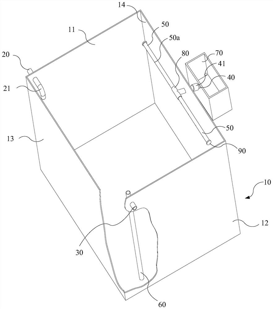
[0031] figure 1 It is a schematic structural diagram of an oil-water separation device provided by an embodiment of the present disclosure. like figure 1 As shown, the oil-water separation device includes a separation box 10 , a liquid inlet pipe 20 , a drain pipe 30 , an oil discharge pipe 40 , an oil collection pipe 50 , a drain deep pipe 60 and an oil collection box 70 . In order to illustrate the structure, figure 1 Part of the side wall of the separation box 10 is omitted in the figure.

[0032] Liquid inlet pipe 20, drain pipe 30 and oil discharge pipe 40 are all installed on the side wall of separation box 10, and one end of liquid inlet pipe 20 is positioned at separation box 10, and the other end of liquid inlet pipe 20...


PUM


Abstract

The invention provides an oil-water separation device, and belongs to the field of oil-water separation. The oil-water separation device comprises a separation box, a liquid inlet pipe, a water drainage pipe, an oil drainage pipe, an oil collection pipe, a water flooding drainage pipe and an oil collection box, the liquid inlet pipe, the water drainage pipe and the oil drainage pipe are all installed on the side wall of the separation box, the oil collection pipe is horizontally arranged in the separation box and communicated with the oil drainage pipe, a plurality of oil collection holes are formed in the pipe wall of the oil collection pipe, the water flooding drainage pipe is located in the separation box, and is communicated with the water drainage pipe, and the oil collection box is located outside the separation box and is communicated with the oil drainage pipe. Due to the fact that the oil collection pipe is not lower than the water drainage pipe and the oil drainage pipe in the vertical direction, oil floating on the water surface can enter the oil collection pipe through a plurality of oil collecting holes in the oil collection pipe, the oil entering the oil collection pipe enters the oil collection box through the oil drainage pipe, the oil-water mixture produced by mechanical equipment can be directly separated, and the oil-water mixture does not need to be transported to a sewage treatment plant for centralized treatment, so that the treatment cost of the oil-water mixture is reduced.

Description

technical field [0001] The present disclosure relates to the field of oil-water separation, in particular to an oil-water separation device. Background technique [0002] Water can play a cooling role in mechanical equipment, and can also have a certain degree of lubrication. For example, in the process of mining coalbed methane, a plunger pump is usually used to provide power for downhole equipment, and the plunger pump needs to be continuously cooled and lubricated by water during the working process. [0003] Since water mainly plays a cooling role and has a limited lubrication effect, lubricating oil is usually used in mechanical equipment. In the process of water circulation, part of the lubricating oil will be taken away, which makes the mechanical equipment produce a large amount of oil-water mixture during the working process. [0004] The direct discharge of the oil-water mixture will cause environmental pollution. Therefore, at present, the oil-water mixture is u...

Claims


Application Information

Patent Timeline
IPC IPC(8): B01D17/032
CPCB01D17/0214
Inventor 原红超贾慧敏吴春升吴定泉霸振赵登刚闻伟樊彬徐小强李鹏鹏赵金利
Owner PETROCHINA CO LTD
Features
  • R&D
  • Intellectual Property
  • Life Sciences
  • Materials
  • Tech Scout
  • Unparalleled Data Quality
  • Higher Quality Content
  • 60% Fewer Hallucinations
Learn More