Dynamic Control System for Airtightness of Dual-flow Vehicles

A dynamically controlled, airtight technology

Active Publication Date: 2022-07-08
CHONGQING CRRC RAILWAY VEHICLES CO LTD
View PDF0 Cites 0 Cited by
  • Summary
  • Abstract
  • Description
  • Claims
  • Application Information

AI Technical Summary

Problems solved by technology

[0004] The present invention intends to provide a dynamic control system for the airtightness of dual-flow vehicles to

Method used


Image

  • Dynamic Control System for Airtightness of Dual-flow Vehicles

Examples


Example Embodiment

[0022] Example 1

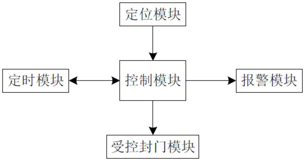
[0023] Dynamic control of dual-flow vehicle air tightness, such as figure 1 Shown: It includes a positioning module, a control module, a controlled damper module, a timing module and an early warning module. The positioning module locates the real-time position of the vehicle, and the positioning module can perform real-time position positioning by sensing the signal of the beacon on the track; the control module obtains Real-time position and send the opening adjustment signal to all controlled damper modules on the vehicle according to the real-time position. The adjustment signal includes the closed signal of the controlled damper module, the opening signal or the opening signal of the preset opening. In Germany, the control module can use the advanced SOC The chip, the controlled air door module includes a fresh air controlled unit and a waste and exhaust air controlled unit. The fresh air controlled unit is installed on the fresh air inlet of the air co...

Example Embodiment

[0030] Embodiment 2

[0031]The difference from Embodiment 1 is that the control module matches the real-time position with the preset position. When the real-time position is the same as the preset position, the control module sends an opening adjustment signal to all the controlled damper modules on the vehicle. When the preset positions are not the same, the control module obtains the real-time vehicle speed and compares it with the preset vehicle speed. The real-time vehicle speed can be obtained directly from the vehicle's control system. When the real-time vehicle speed is greater than the preset vehicle speed, the control module will report to all the controlled damper modules on the vehicle. Send the opening adjustment signal; when the real-time vehicle speed is greater than the preset vehicle speed, the control module obtains the timing duration of the timing module for judgment, and when the timing duration is greater than the threshold, the control module stores the ...

Example Embodiment

[0033] Embodiment 3

[0034] The difference from the second embodiment is that the control module calculates the spacing value between the real-time position and the supplementary adjustment position, the real-time position and the supplementary adjustment position can be represented by coordinate values, and the calculation of the spacing value can be performed according to the coordinate value, and the control module judges the spacing. Whether the value is smaller than the preset distance, when the distance value is smaller than the preset distance, the control module calculates the acceleration value according to the real-time vehicle speed obtained successively, and subtracts the real-time speed obtained earlier from the real-time vehicle speed obtained later to obtain the acceleration value. The acceleration value sends the opening adjustment signal to the controlled air door module on the vehicle in the direction from the front to the rear of the vehicle. For example, th...


PUM


Abstract

The invention relates to the technical field of train ventilation control, in particular to a dynamic control system for the air tightness of a dual-flow vehicle, comprising a positioning module, a control module, a controlled damper module and a timing module. The positioning module locates the real-time position of the vehicle, and the control module obtains Real-time position and according to the real-time position send the opening adjustment signal to all the controlled damper modules on the vehicle, and send the timing signal to the timing module to start the timing. Whether the actual opening reaches the preset opening, if not, the control module determines whether the actual opening is less than the preset opening, and when the actual opening is less than the preset opening, the control module sends a reciprocating adjustment signal to the controlled damper module. The present invention can automatically and dynamically adjust the air pressure in the vehicle compartment through the controlled air door module, thereby reducing the variation of the air pressure when the vehicle is running in two different environments.

Description

technical field [0001] The invention relates to the technical field of train ventilation control, in particular to a dynamic control system for the air tightness of a dual-flow vehicle. Background technique [0002] Dual-flow vehicles need to travel between areas with different power supply voltages. During cross-area driving, dual-flow vehicles use air conditioning units to ensure a comfortable air pressure in the cabin. Due to the long mileage of dual-flow vehicles traveling across regions, the environment along the line is complex and changeable, the distance between stations is large, and the driving speed is fast, the air pressure control in the cabin based on the air conditioning unit needs to be dynamically controlled to ensure a comfortable air pressure in the cabin. [0003] At present, the air pressure in the rail vehicle compartment is maintained by a single-speed fan or a two-speed fan, and the fresh air door for fresh air generally has only two states of opening...

Claims


Application Information

Patent Timeline
IPC IPC(8): B61D27/00
CPCB61D27/0009Y02T30/00
Inventor 姚鸿洲水新虎姚平王麒皓杨芬陈亮廖泳竣周汝松何英杰
Owner CHONGQING CRRC RAILWAY VEHICLES CO LTD
Why Eureka
Try Eureka