Cap screwing method

A tube cap and gripper technology, applied in screw caps and other directions, can solve the problems of inability to work together at the same time, high cost, and large footprint.

Inactive Publication Date: 2021-10-26
江苏迅睿生物技术有限公司
View PDF8 Cites 1 Cited by
  • Summary
  • Abstract
  • Description
  • Claims
  • Application Information

AI Technical Summary

Problems solved by technology

[0006] Above-mentioned prior art mostly all is to carry out capping for single test tube
When the amount of detection is large, the operating efficiency of the above equipment cannot adapt
[0007] However, if the multi-channel automatic unscrewing / tightening of the tube cap is realized, it is not simply to set the number of the aforementioned prior art capping mechanisms to multiple, but to simply set multiple "single-channel electric rotary grippers" , will face many problems, cost a lot, occupy a large area, cannot work together at the same time, etc.

Method used


Image

  • Cap screwing method
  • Cap screwing method

Examples


specific Embodiment approach

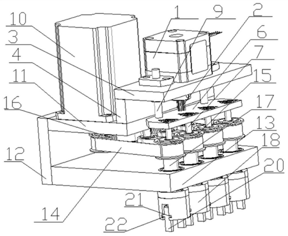
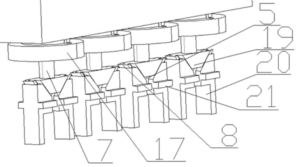
[0035]As shown in 1-2, the jaw motor 1 drives the lead screw 2 to rotate, and the lead screw 2 rotates to drive the lifting plate 6 to move up and down. The linkage with the ball screw 2 is a thread, the lifting shaft 7 is fixedly connected with the lifting plate 6, the lifting shaft 7 can follow the lifting plate 6 to move up and down, the jaw guide block 19 is fixedly connected with the lifting shaft 7, and the jaw guide block 19 can be Following the lifting shaft 7 to move up and down, the jaws 20 are provided with a chute 5, and the jaw guide block 19 is provided with two sliders 8 respectively adapted to the chute 5 on the two jaws 20. In addition, the jaws 20 Symmetrical bosses 21 are also set on the top, and grooves 22 that are respectively adapted to the symmetrical bosses 21 on the two jaws 20 are arranged on the jaw limit block 18, and the bosses 21 can be horizontally positioned in the grooves 22. When the jaw guide block 19 moves up and down, the jaw 20 moves horiz...


PUM


Abstract

The invention discloses a cap screwing method. According to the technical key points, the cap screwing method comprises the following steps that S1, a pipe cap is clamped, specifically, a clamping jaw motor is started, so that the pipe cap is clamped by clamping jaws; and S2, the pipe cap is screwed, specifically, after a rotating motor is started, a driving wheel is driven to rotate forwards or reversely, the driving wheel drives synchronous wheels to rotate forwards or reversely through a synchronous belt, the four synchronous wheels correspond to the four clamping jaws correspondingly, and forward rotation or reverse rotation of the synchronous wheels drives the four clamping jaws to rotate forwards or reversely, so that full-automatic unscrewing / screwing of a sampling pipe cap is realized. By the adoption of the cap screwing method, four pipe caps can be screwed / unscrewed synchronously.

Description

technical field [0001] The application belongs to the field of fully automatic capping equipment, and in particular relates to a capping method. Background technique [0002] Nowadays, in medical testing, the collected samples are stored in test tubes or sample tubes with screw caps, and after people collect the samples, they are tested uniformly. [0003] In order to improve the efficiency of detection, many research institutions have conducted research on how to automatically unscrew / tighten tube caps. [0004] Such as: CN210214753U, a test tube automatic cap sealing device: it includes a first transmission mechanism, a cap sealing cap assembly, a pressure mechanism and a feeding device; the cap sealing cap assembly includes a first suction plate, a second suction plate and a fixed bracket ; The first suction plate includes a first plate body, a second plate body and a first lifting device; the lower surface of the second plate body is provided with a first suction head; ...

Claims


Application Information

Patent Timeline
Patent Type & Authority Applications(China)
IPC IPC(8): B67B3/20
CPCB67B3/20
Inventor 王威陈振聂晶
Owner 江苏迅睿生物技术有限公司
Why Eureka
Try Eureka