Optical system, camera module and electronic equipment
What is AI technical title?
AI technical title is built by PatSnap AI team. It summarizes the technical point description of the patent document.
An optical system, optical axis technology, used in optics, optical components, instruments, etc.
Active Publication Date: 2021-10-26
JIANGXI JINGCHAO OPTICAL CO LTD
View PDF5 Cites 2 Cited by
Summary
Abstract
Description
Claims
Application Information
AI Technical Summary
This helps you quickly interpret patents by identifying the three key elements:
Problems solved by technology
Method used
Benefits of technology
Problems solved by technology
[0005] Based on this, it is necessary to provide an optical system, a camera module and an electronic device for how to better realize the problem of how to improve the imaging effect while taking into account the optical characteristics of the large image surface.
Method used
Image
Click on the blue label to locate the original text in one second.
Reading with bidirectional positioning of images and text.
Examples
no. 1 example
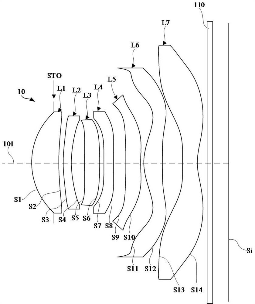
[0070] refer to figure 1 In the first embodiment, the optical system 10 includes an aperture stop STO, a first lens L1 with positive refractive power, a second lens L2 with negative refractive power, and a second lens L2 with positive refractive power from the object side to the image side. Three lenses L3, a fourth lens L4 with negative refractive power, a fifth lens L5 with negative refractive power, a sixth lens L6 with positive refractive power, and a seventh lens L7 with negative refractive power.
[0071] The surface shape of each lens surface in the optical system 10 is as follows:
[0072] The object side S1 of the first lens L1 is convex at the near optical axis, and the image side S2 is concave at the near optical axis; the object side S1 of the first lens L1 is concave at the circumference, and the image side S2 is convex at the circumference;
[0073] The object side S3 of the second lens L2 is convex at the near optical axis, and the image side S4 is concave at t...
no. 2 example
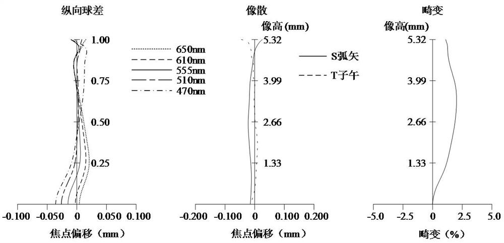
[0106] refer to image 3 In the second embodiment, the optical system 10 includes an aperture stop STO, a first lens L1 with positive refractive power, a second lens L2 with negative refractive power, and a second lens L2 with negative refractive power from the object side to the image side. Three lenses L3, a fourth lens L4 with negative refractive power, a fifth lens L5 with negative refractive power, a sixth lens L6 with positive refractive power, and a seventh lens L7 with negative refractive power.
[0107] The surface shape of each lens surface in the optical system 10 is as follows:
[0108] The object side S1 of the first lens L1 is convex at the near optical axis, and the image side S2 is concave at the near optical axis; the object side S1 of the first lens L1 is concave at the circumference, and the image side S2 is convex at the circumference;
[0109] The object side S3 of the second lens L2 is convex at the near optical axis, and the image side S4 is concave at ...
no. 3 example
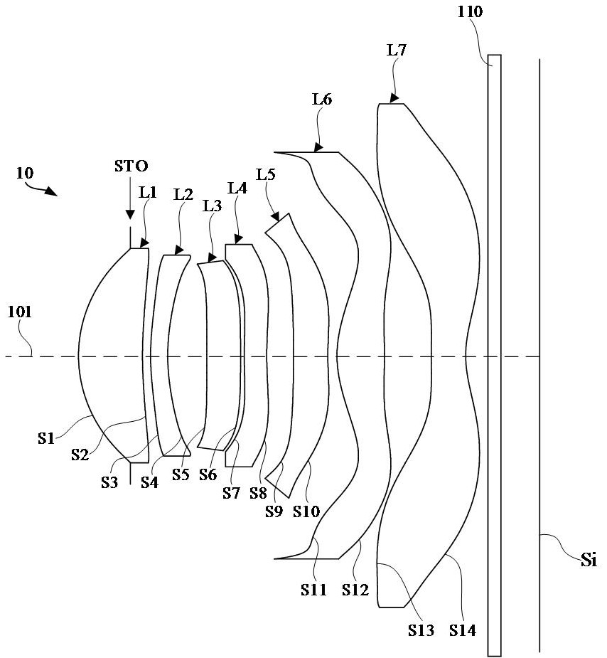
[0124] refer to Figure 5 In the third embodiment, the optical system 10 includes an aperture stop STO, a first lens L1 with positive refractive power, a second lens L2 with negative refractive power, and a second lens L2 with positive refractive power from the object side to the image side. Three lenses L3, a fourth lens L4 with negative refractive power, a fifth lens L5 with negative refractive power, a sixth lens L6 with positive refractive power, and a seventh lens L7 with negative refractive power.
[0125] The surface shape of each lens surface in the optical system 10 is as follows:
[0126] The object side S1 of the first lens L1 is convex at the near optical axis, and the image side S2 is concave at the near optical axis; the object side S1 of the first lens L1 is concave at the circumference, and the image side S2 is convex at the circumference;
[0127] The object side S3 of the second lens L2 is convex at the near optical axis, and the image side S4 is concave at ...
PUM
Property
Measurement
Unit
Effective focal length
aaaaa
aaaaa
Maximum viewing angle
aaaaa
aaaaa
Optical length
aaaaa
aaaaa
Abstract
The invention relates to an optical system, a camera module and electronic equipment. The optical system sequentially comprises a first lens element with positive refractive power from an object side to an image side along an optical axis, a second lens element with negative refractive power, a third lens element, a fourth lens element, a fifth lens element with negative refractive power, a sixth lens element with positive refractive power and a seventh lens element with negative refractive power, wherein the second lens element with negative refractive power has a convex object-side surface and a concave image-side surface in a paraxial region, respectively. the third lens is further included; the fourth lens is further included; the fifth lens element with negative refractive power is further included; the sixth lens element with positive refractive power has an object-side surface being convex in a paraxial region thereof, and at least one of the object-side surface and the image-side surface is provided with an inflection structure; for the seventh lens element with negative refractive power, the image-side surface is concave in a paraxial region thereof, and at least one of the object-side surface and the image-side surface is provided with an inflection structure; the optical system satisfies the following conditional expression, ImgH / FNO is greater than 3.00 mm; ImgH is half of the image height corresponding to the maximum field angle of the optical system, and FNO is the number of apertures of the optical system. The optical system of the above design has a large image plane and high imaging quality.
Description
technical field [0001] The invention relates to the technical field of photography and imaging, in particular to an optical system, a camera module and electronic equipment. Background technique [0002] In recent years, because the optical lens has the function of acquiring image information, the optical lens has become the main module for image capture of electronic products. At the same time, with the rapid improvement of people's living standards and the rapid development of science and technology, people have higher and higher requirements for the imaging quality of optical lenses. Therefore, how to improve the optical characteristics of optical lenses to improve imaging effects has become an urgent problem. question. [0003] In related technologies, usually by increasing the number of lenses of the optical lens, or configuring parameters such as lens refractive power and surface shape of the lens, the optical lens can obtain higher imaging quality. However, due to t...
Claims
Application Information
Patent Timeline
Application Date:The date an application was filed.
Publication Date:The date a patent or application was officially published.
First Publication Date:The earliest publication date of a patent with the same application number.
Issue Date:Publication date of the patent grant document.
PCT Entry Date:The Entry date of PCT National Phase.
Estimated Expiry Date:The statutory expiry date of a patent right according to the Patent Law, and it is the longest term of protection that the patent right can achieve without the termination of the patent right due to other reasons(Term extension factor has been taken into account ).
Invalid Date:Actual expiry date is based on effective date or publication date of legal transaction data of invalid patent.

