A self-calibrating high-precision digital time conversion circuit

A digital-to-time conversion and analog-to-digital conversion technology, applied in the fields of digital time conversion circuits and high-precision digital time conversion circuits, can solve problems such as offside offset of output clock signals, achieve good reliability, achieve self-calibration, and reduce quantization noise Effect

Active Publication Date: 2022-04-05
DALIAN UNIV OF TECH
View PDF18 Cites 0 Cited by
  • Summary
  • Abstract
  • Description
  • Claims
  • Application Information

AI Technical Summary

Problems solved by technology

However, for current-mode digital-to-analog conversion circuits, the reference current source in the circuit is affected by changes in temperature, process, and voltage, and the output reference current will change with the
For a high-precision digital time conversion circuit, a small current change will cause an offside shift in its output clock signal

Method used


Image

  • A self-calibrating high-precision digital time conversion circuit
  • A self-calibrating high-precision digital time conversion circuit
  • A self-calibrating high-precision digital time conversion circuit

Examples


Embodiment 1

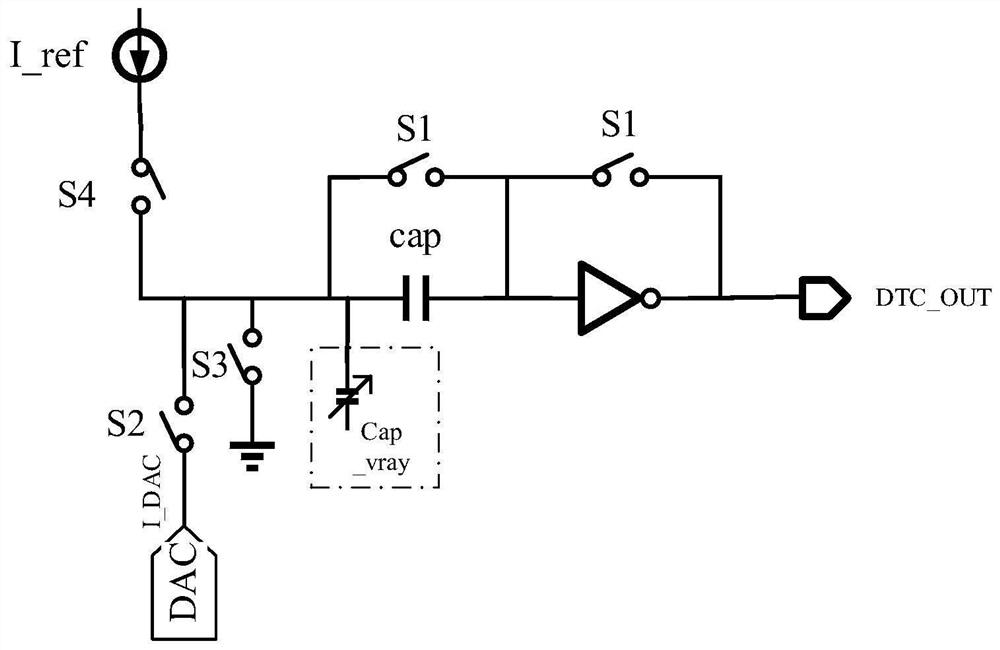
[0025] Such as figure 1 As shown, this embodiment discloses a self-calibrating high-precision digital time conversion circuit, including: a digital-to-analog converter DAC, a capacitor array, a switch array, and an inverter; the digital-to-analog converter DAC is connected to a capacitor array; the capacitor array and The inverter is connected; the inverter is connected to the output terminal DTC_OUT; the digital-to-analog converter DAC, the capacitor array, the inverter and the ground terminal are respectively provided with a switch array; the capacitor array includes a fixed capacitor cap and a variable capacitor cap_vary; digital-to-analog conversion The DAC charges the capacitor array according to the input digital control word. The self-calibration technology uses feedback to feed back the change signal of the reference current source to the variable capacitance capacitor cap_vary, thereby compensating and calibrating the capacitance value of the capacitor array; the inve...

Embodiment 2

[0028] Such as figure 1 As shown, the digital-to-analog converter DAC of this embodiment is a current-mode digital-to-analog converter based on a current steering structure. Its structure is mainly composed of a reference current source, a multi-channel current mirror branch and a control switch. The width-to-length ratios of the transistors in each current mirror branch are different. According to the number of digits of the designed digital-to-analog converter, the ratio of the width-to-length ratios is 2 0 ,2 1 ,2 2 ,2 3 ,……,2 n. The control switch is controlled by a digital signal, by controlling the opening and closing of each current mirror branch, so as to realize different magnitudes of current output. Based on this method, the charging current of the capacitor array can be precisely controlled, and with the improvement of the precision of the digital-to-analog converter, the precision of the corresponding digital time conversion circuit is also improved. For ex...

Embodiment 3

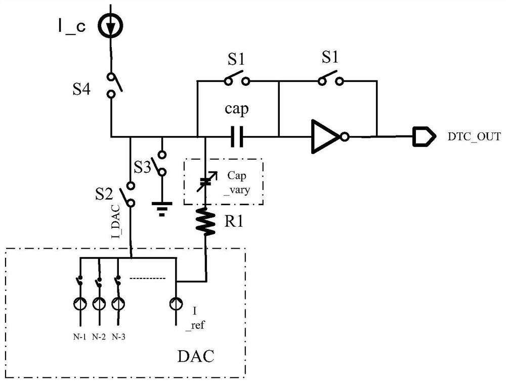
[0044] This embodiment also includes: a first resistor R1; the variable capacitor cap_vary is a voltage-controlled capacitor; one end of the first resistor R1 is connected to the reference current source of the digital-to-analog converter DAC, and the other end is connected to the variable capacitor cap_vary; through the first resistor R1 The change of the reference current is sampled in real time, and the change of the reference current is reflected on the voltage change of the first resistor R1, and the change of the capacitance value of the variable capacitor cap_vary is controlled, so as to calibrate and compensate the capacitance value of the capacitor array.

[0045] Specifically, as figure 2 As shown, the variable capacitor array is composed of voltage-controlled capacitors. One end of the first resistor R1 is connected to the reference current source of the DAC, and the other end is connected to the voltage-controlled capacitor (cap_vary). Through the first resistor ...


PUM


Abstract

The invention provides a self-calibrating high-precision digital time conversion circuit. The invention comprises: a digital-to-analog converter DAC, a capacitor array, a switch array composed of a plurality of switches, and an inverter; the digital-to-analog converter DAC is connected to the capacitor array; the capacitor array is connected to the inverter; the inverter is connected to an output end; The digital-to-analog converter DAC, the capacitor array, the inverter, and the ground terminal are respectively provided with switches; the capacitor array includes a fixed-capacity capacitor cap and a variable-capacity capacitor cap_vary; the digital-to-analog converter DAC according to the input representing the time delay The control word charges the capacitor array, and feeds back the current change of the reference current source to the variable capacitor cap_vary, thereby compensating and calibrating the capacitance value of the capacitor array; the inverter outputs a clock signal according to the capacitance value of the compensated and calibrated capacitor array . It solves the technical problem in the prior art that the reference current is affected by changes in temperature, process and voltage, resulting in an off-side shift in the output clock signal.

Description

technical field [0001] The invention relates to digital time conversion circuit technology, in particular to a self-calibrating high-precision digital time conversion circuit, which belongs to the technical field of digital-analog hybrid integrated circuits. Background technique [0002] In recent years, with the continuous development of technology, phase-locked loop (PLL, Phase Lock Loop) is widely used in communication, AI, Internet of Things, sensors and other applications to generate basic clock signals for RF transceivers, timing control circuits and other circuits middle. It has a crucial impact on the performance of the circuit such as noise. [0003] According to the type of phase-locked loop, it can be divided into analog charge pump phase-locked loop (CPPLL) and all-digital phase-locked loop (ADPLL). Among them, the analog charge pump phase-locked loop has good phase noise performance, but the design complexity and power consumption are higher than the all-digit...

Claims


Application Information

Patent Timeline
Patent Type & Authority Patents(China)
IPC IPC(8): G04F10/00
CPCG04F10/005
Inventor 申人升周滔常玉春王志硕刘宇帆叶伟成张璐李技烨刘炯晗周义喆牛仕泽
Owner DALIAN UNIV OF TECH
Why Eureka
Try Eureka