Video signal processing apparatus

a video signal and processing apparatus technology, applied in the field of video signal processing apparatus, can solve the problems of inability to accurately detect the time of the time, so as to reduce quantization noise, easy to generate clocks, and constant supply of stable clocks

Inactive Publication Date: 2006-08-24
SOCIONEXT INC
View PDF15 Cites 13 Cited by
  • Summary
  • Abstract
  • Description
  • Claims
  • Application Information

AI Technical Summary

Benefits of technology

[0021] According to a fourth aspect of the present invention, in the video signal processing apparatus defined in any of Claims 1 to 3, the second clock generation circuit comprises: an accumulation circuit for inputting a set value as a reference of an output frequency, and adding the set value for each reference clock; a memory for previously storing sinusoidal data or periodical data, and taking out the data according to an output value of the accumulation circuit; a D / A converter for converting the output data from the memory into an analog signal; a filter processing circuit for reducing quantization noise in the analog signal; and a multiply circuit for multiplying, by N (N: integer), a signal which has periodicity and is output from the filter processing circuit; and the second clock generation circuit generates a second clock. Therefore, when a reference clock is inputted, sinusoidal waveform data is outputted from a ROM in accordance with a set value of a register, regardless of a reset signal, and thereby the duty of the clock is not likely to change dependent on the count value, resulting in constant supply of stable clocks.
[0022] As described above, a clock generation circuit in a video signal processing apparatus according to the present invention can easily generate clocks for pixel display and subsequent-stage processings by inputting a set value corresponding to the clock frequency of the pixel display. Further, even when a non-standard signal of VTR or the like is inputted, the cycles of clocks to be used for processings after memory reading are not shortened, and the cycles can be kept constant, thereby avoiding timing errors in video processing using the clocks corresponding to the clock frequencies for the pixel display and the subsequent-stage processings.
[0023] Further, in the video signal processing apparatus according to the present invention, it is possible to constitute a system which does not use a high-power multiply PLL that requires a lot of man-hours for designing and verification when generating a clock corresponding to a clock frequency of a pixel display, and further, it is possible to establish a video signal processing system which requires no considerations on influences by jitter and the like.

Problems solved by technology

In the clock generation circuit of the conventional video signal processing circuit, however, when resetting the counter with the reset signal which is generated by the horizontal sync signal at the clock outputted from the second clock generation circuit, if a horizontal sync signal that is an integer multiple of the cycle of the output clock is not inputted or if the input clock is a non-standard signal having a deteriorated sync signal such as VTR, the length of the clock cycle is undesirably shortened or the ratio between the Low period and the High period of the clock, i.e., the duty ratio, undesirably loses accuracy.
Therefore, when the conventional clock generation circuit is applied to the video signal processing apparatus, in the processing circuit that is operated with the second clock, a timing error occurs in a combination circuit due to the short clock cycle, leading to outputting of unexpected data.
Further, in the clock generation circuit of the conventional video signal processing circuit, since the count value is reset by the horizontal sync signal, the length of the clock cycle is undesirably shortened depending on the timing at which the horizontal sync signal is inputted, leading to discontinuous output clocks.
Therefore, when the clock frequency for driving a liquid crystal panel exceeds 80 MHz or 100 MHz, it is necessary for the clock oscillator to input a clock of a frequency higher than that of the panel driving clock, resulting in a noise source as well as an increase in power consumption.
Accordingly, the conventional clock generation circuit is not practical.
Accordingly, it is necessary to perform verification with many combinations when a high-power multiply PLL is designed, leading to a lot of time required for designing.
Further, it is difficult to reduce jitters of clocks, and redesign is needed at every miniaturization of semiconductor processing.

Method used


Image

  • Video signal processing apparatus
  • Video signal processing apparatus
  • Video signal processing apparatus

Examples


embodiment 1

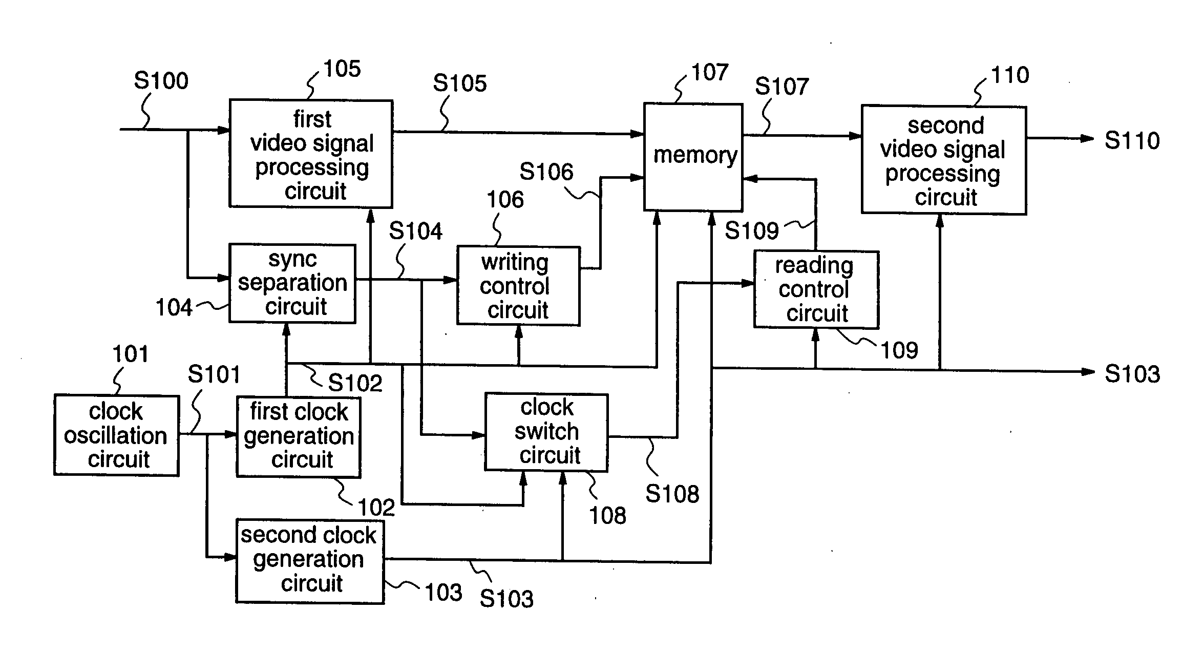
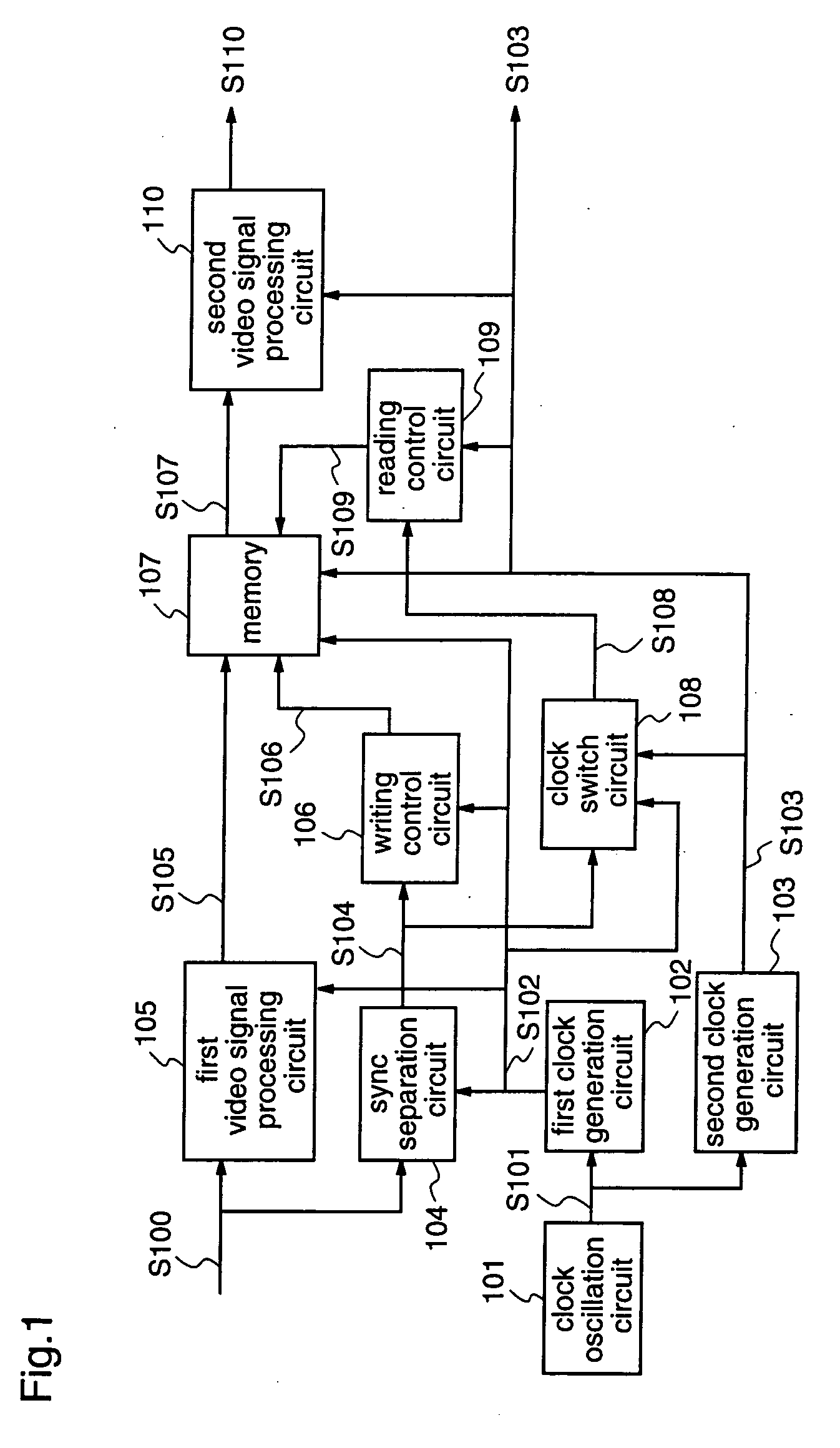
[0033]FIG. 1 is a block diagram illustrating the construction of a video signal processing apparatus according to a first embodiment of the present invention.

[0034] With reference to FIG. 1, the video signal processing apparatus comprises a clock oscillation circuit 101, a first clock generation circuit 102, a second clock generation circuit 103, a sync separation circuit 104, a first video signal processing circuit 105, a writing control circuit 106, a memory 107 capable of controlling writing and reading with different clocks, a sync signal clock switch circuit 108, a reading control circuit 109, and a second video signal processing circuit 110.

[0035] The clock oscillation circuit 101 oscillates a reference clock S101 using crystal or the like. The reference clock S101 is input to the first clock generation circuit 102. When the inputted video signal S100 includes a burst signal, the first clock generation circuit 102 locks the phase to the burst signal to output a 4 fsc clock (...

embodiment 2

[0053] Next, a video signal processing apparatus according to a second embodiment of the present invention will be described.

[0054]FIG. 5 is a block diagram illustrating an example of a construction of a video signal processing apparatus according to the second embodiment.

[0055] With reference to FIG. 5, the video signal processing apparatus according to the second embodiment is provided with a clock oscillation circuit 101, a first clock generation circuit 102, a second clock generation circuit 103, a sync separation circuit 104, a first video signal processing circuit 105, a first writing control circuit 106, a first memory 107, a first clock switch circuit 509, a multiply circuit 501, a first reading control circuit 502, a third video signal processing circuit 503, a second writing control circuit 504, a second memory 505, a second clock switch circuit 506, a second reading control circuit 507, and a second video signal processing circuit 508. The same constituents as those of ...


PUM


Abstract

A video signal processing apparatus is provided with a first clock generation circuit for generating a first clock synchronized with an input signal; a second clock generation circuit for receiving a set value to be a reference of an output frequency, adding the set value for every reference clock, extracting data according to the cumulative value, converting the data into an analog signal, reducing quantization noise, and multiplying the analog signal, thereby to obtain a second clock; and a clock switch circuit for generating a sync signal that is switched to the second clock, by using a sync signal generated with the first clock; and video signal processing is carried out using the second clock that is generated according to the resolution of a pixel display.

Description

FIELD OF THE INVENTION [0001] The present invention relates to a video signal processing apparatus and, more particularly, to a video signal processing apparatus which is provided with a clock generation circuit for generating clocks for a pixel display unit and a subsequent-stage system, and is constituted by plural clocks when performing video signal processing. BACKGROUND OF THE INVENTION [0002] In recent years, various resolutions have appeared for pixel display units such as a liquid crystal panel and a PDP, and the clock frequency for driving such panel differs from panel to panel. In a clock generation circuit or a video signal processing which can generate a clock according to the clock frequency for operating a panel, it is necessary to display video on a pixel display unit after switching to the clock frequency of the panel. [0003] For example, in a clock generation circuit of a conventional video signal processing apparatus described in Japanese Published Patent Applicati...

Claims


Application Information

Patent Timeline
Patent Type & Authority Applications(United States)
IPC IPC(8): H04N9/44H04N5/04H04N9/64H04N5/14G09G3/20G09G3/36G09G5/00G09G5/18G09G5/391
CPCG09G5/005G09G5/008H04N5/932H04N9/44H04N9/64
Inventor TANIGAWA, SATORU
Owner SOCIONEXT INC
Why Eureka
Try Eureka