Moving picture encoding apparatus, moving picture encoding method, moving picture encoding program, moving picture decoding apparatus, moving picture decoding method, and moving picture decoding program

a technology of moving pictures and encoding methods, applied in the direction of color televisions with bandwidth reduction, instruments, television systems, etc., can solve the problems of reducing the quality of reference images and failure to reduce data volumes in sufficient ways, so as to reduce the noise of moving pictures, improve encoding efficiency, and reduce the data volume of moving pictures

Inactive Publication Date: 2005-10-20
NTT DOCOMO INC
View PDF1 Cites 16 Cited by
  • Summary
  • Abstract
  • Description
  • Claims
  • Application Information

AI Technical Summary

Benefits of technology

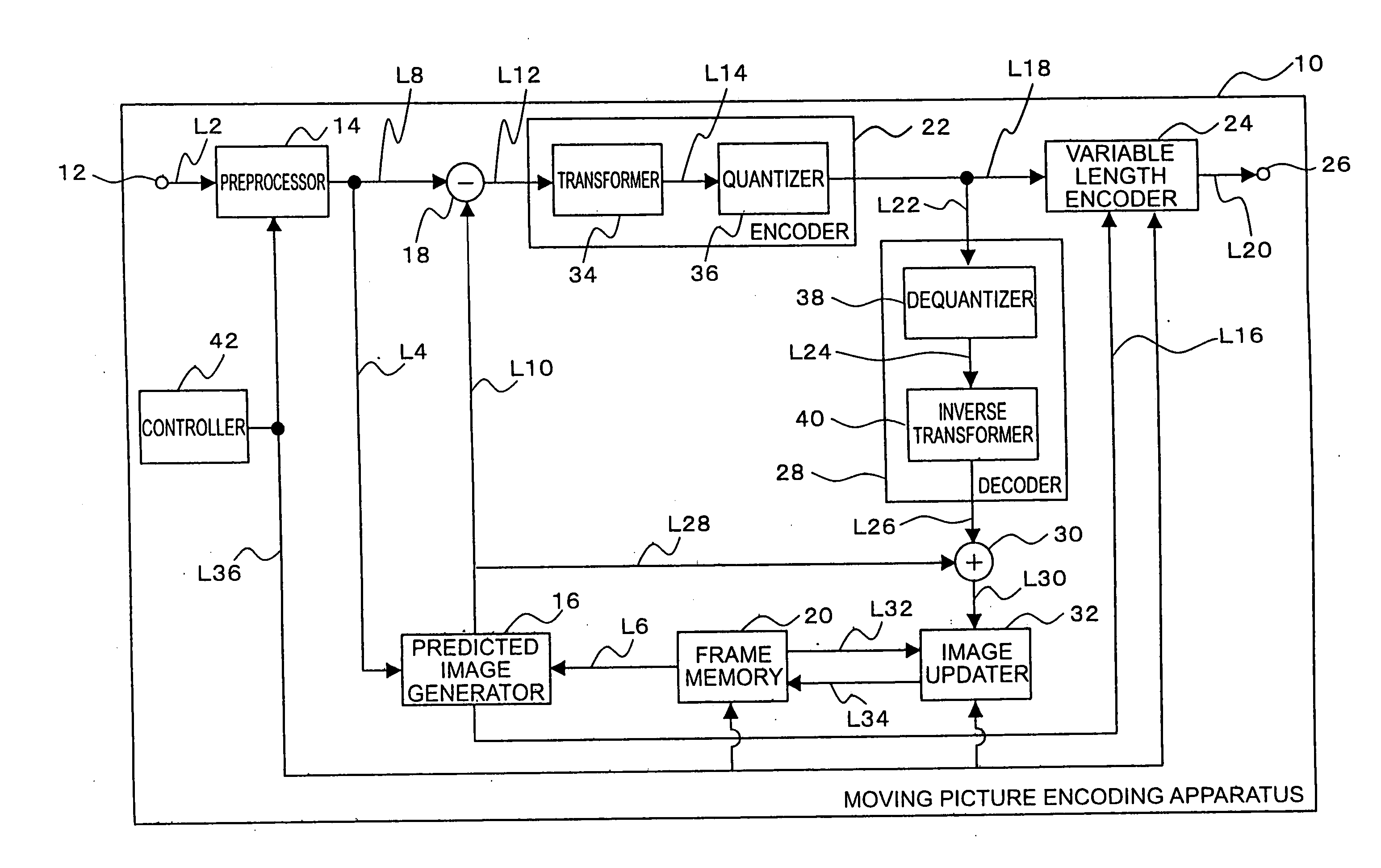
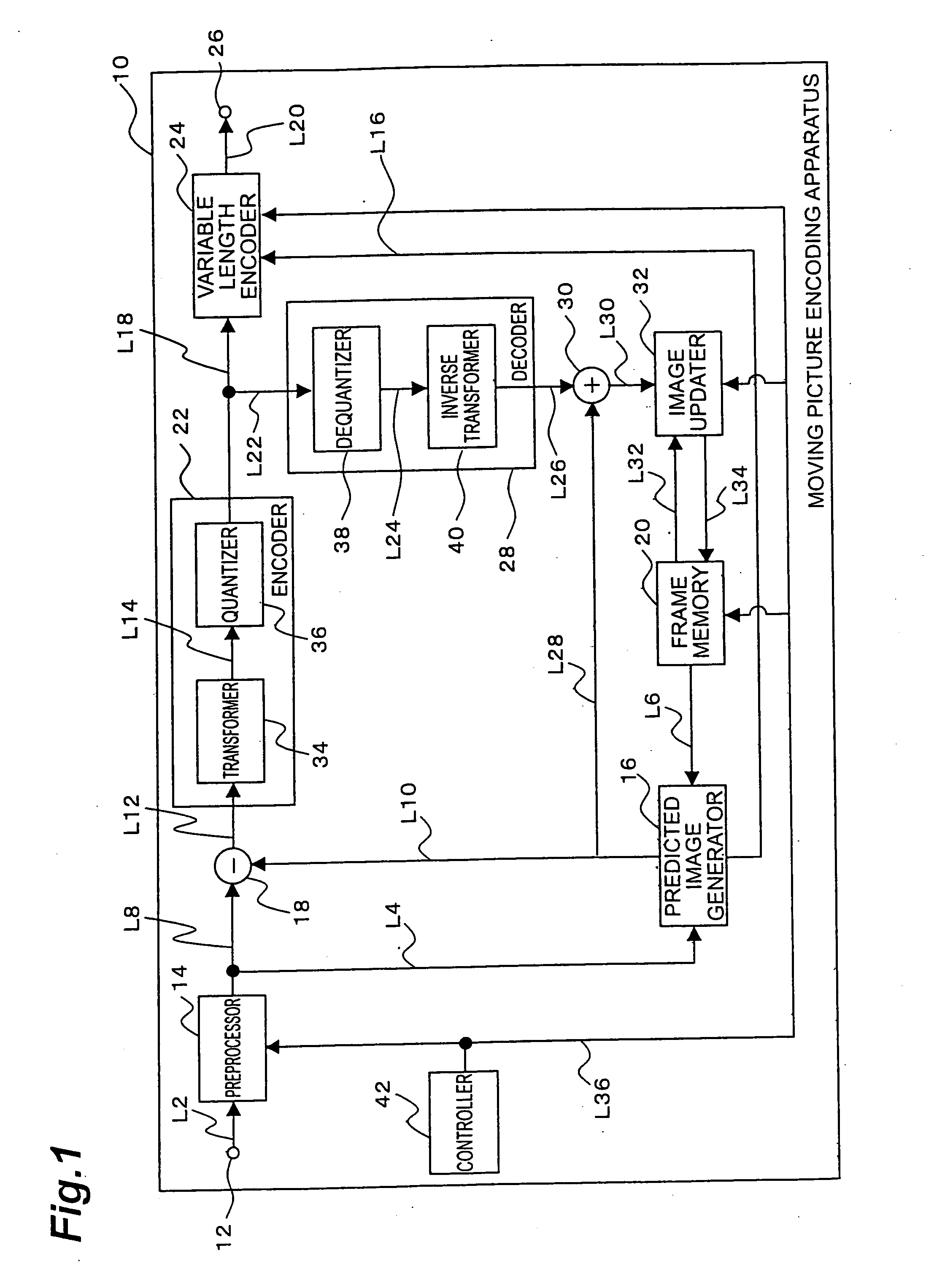
[0010] The present invention associated with the foregoing encoding of the moving picture involves performing the weighted summation of the first image which is one of the reproduced image and the reference image previously stored in the storing means, and the second image which is the other of the reproduced image and the reference image, to generate the updated image. This updated image is used as a reference image for generating a predicted image for another target image. Therefore, the present invention uses the reference image in which noise is reduced by averaging based on the summation, so as to reduce the data volume of the moving picture by encoding, thereby improving the encoding efficiency. Furthermore, the present invention generates the updated image resulting from averaging of the reproduced image and the reference image, whereby the updated image can reflect details of the image which are absent in the reproduced image or in the reference image. Therefore, the data volume of the moving picture by encoding is further reduced.
[0011] One of the various known noises generated in the reproduced image is noise caused by the block boundary effect of making a large change of pixel values at a boundary between blocks. A known technique for reducing the noise due to the block boundary effect is to apply a deblocking filter to the vicinity of the boundary between blocks in the reproduced image. However, the deblocking filter cannot reduce the noise caused inside a block. The present invention reduces the noise in the reference image by the averaging based on the summation, so as to reduce the noise inside the block.
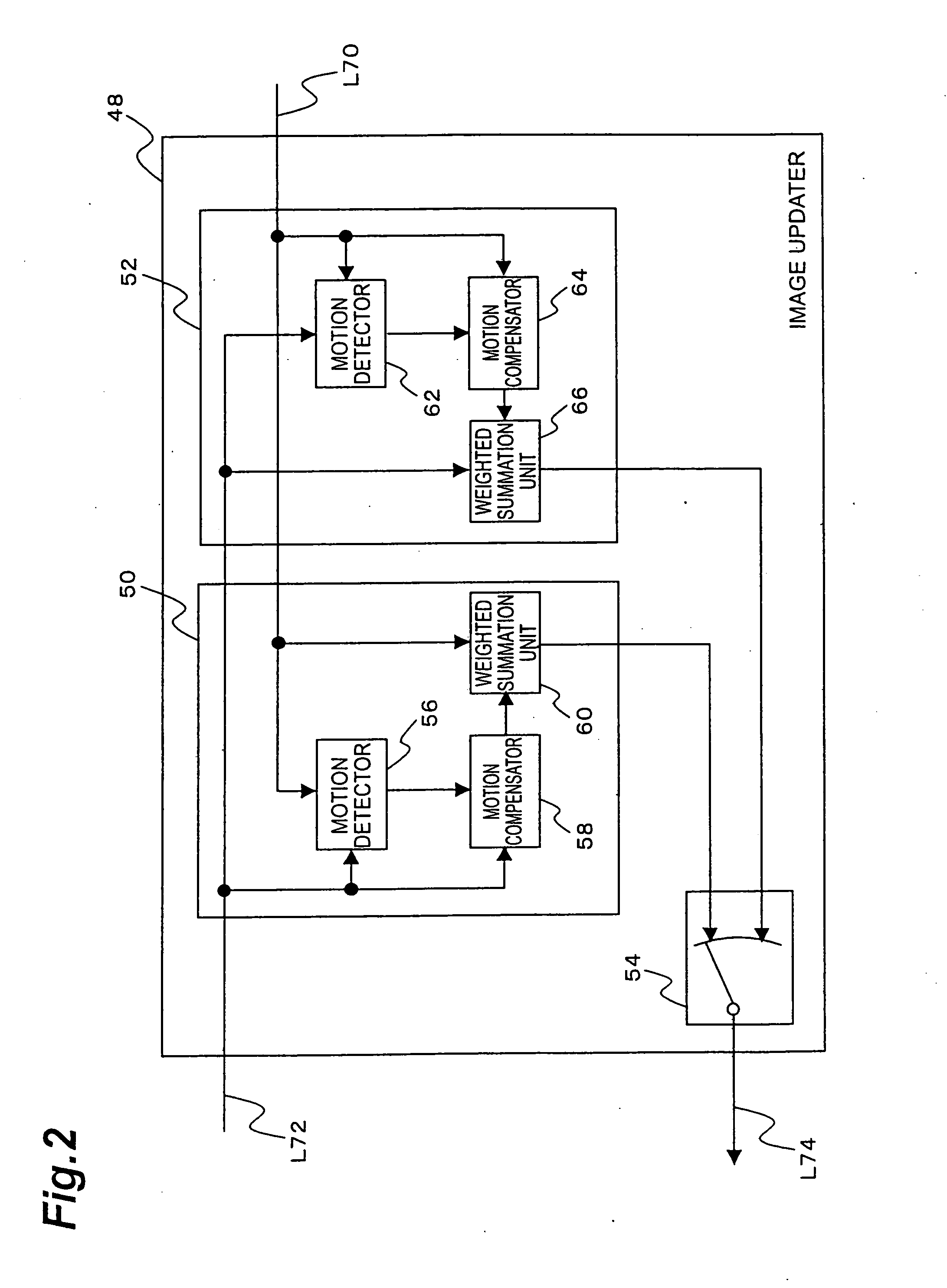
[0012] Furthermore, the bidirectional prediction is known as a technique for reducing the quantization noise or the like which is one of the noise components generated in the reproduced image. In the bidirectional prediction, two motion amounts (first motion amount and second motion amount) are acquired for a processing target block. The first motion amount is an amount of motion of the processing target block to a forward reference image in the time direction. The second motion amount is an amount of motion of the processing target block to a backward reference image in the time direction. In the bidirectional prediction, a first predicted image is obtained from the first motion amount, a second predicted image is obtained from the second motion amount, and a predicted image obtained by averaging of the first predicted image and the second predicted image is used. However, this predicted image is used for a specific processing target block, but cannot be used as a reference image in subsequent processing of another processing target block. In the bidirectional prediction, therefore, the effect of reducing the noise by averaging is not utilized in subsequent processing. On the other hand, the present invention involves storing the updated image with noise reduced by averaging, as a reference image into the storing means and using the updated image for generation of a predicted image in subsequent processing. Therefore, the present invention also utilizes the effect of the noise reduction by averaging, in processing of another target image.

Problems solved by technology

If the reproduced image contains noise, it will degrade the quality as a reference image.
As a result, the difference becomes large between the predicted image and the target image, so as to result in failure in sufficient reduction of data volume.

Method used


Image

  • Moving picture encoding apparatus, moving picture encoding method, moving picture encoding program, moving picture decoding apparatus, moving picture decoding method, and moving picture decoding program
  • Moving picture encoding apparatus, moving picture encoding method, moving picture encoding program, moving picture decoding apparatus, moving picture decoding method, and moving picture decoding program
  • Moving picture encoding apparatus, moving picture encoding method, moving picture encoding program, moving picture decoding apparatus, moving picture decoding method, and moving picture decoding program

Examples


Embodiment Construction

[0054] The preferred embodiments of the present invention will be described below in detail with reference to the drawings. Identical or equivalent portions will be denoted by the same reference symbols in each of the drawings.

[0055]FIG. 1 is an illustration showing a configuration of a moving picture encoding apparatus according to an embodiment of the present invention. The moving picture encoding apparatus 10 shown in FIG. 1 can be physically composed of a computer comprising a CPU (central processing unit), a storage device such as a memory, a display unit, a communication device, and so on. The moving picture encoding apparatus 10 may be a mobile telecommunications terminal such as a cell phone. Namely, a variety of information processing equipment can be applied to the moving picture encoding apparatus 10.

[0056] As shown in FIG. 1, the moving picture encoding apparatus 10 is functionally composed of an input terminal 12, a preprocessor 14, a predicted image generator (predic...


PUM


Abstract

In a moving picture encoding apparatus 10, as an embodiment of the present invention, a predicted image generator 16 generates a predicted image with respect to a target image, using a reference image stored in a frame memory 20. A difference image generator 18 performs a difference operation between the target image and the predicted image to generate a difference image. An encoder 22 encodes the difference image to generate an encoded difference signal. A decoder 28 decodes the encoded difference signal to generate a decoded difference image. A reproduced image generator 30 performs a summation of the decoded difference image and the predicted image to generate a reproduced image. An image updater 32 performs a weighted summation of a first image which is one of the reproduced image and the reference image, and a second image which is the other of the reproduced image and the reference image, to generate an updated image. The updated image is stored into the frame memory 20 to be used as a reference image in encoding of another target image.

Description

BACKGROUND OF THE INVENTION [0001] 1. Field of the Invention [0002] The present invention relates to a moving picture encoding apparatus, a moving picture encoding method, a moving picture encoding program, a moving picture decoding apparatus, a moving picture decoding method, and a moving picture decoding program. [0003] 2. Related Background Art [0004] The compression coding technologies are used in order to achieve efficient transmission and storage of a moving picture. One of the known compression coding technologies is the interframe coding method. In the interframe coding method, an image is divided into a plurality of blocks of a predetermined size and a coding process is carried out on a block-by-block basis. In this coding process, a reproduced image of another image adjacent in the time direction is used as a reference image, and a predicted image is generated with respect to a target image as an object to be encoded. Here the reproduced image is a reconstruction of an ima...

Claims


Application Information

Patent Timeline
Patent Type & Authority Applications(United States)
IPC IPC(8): H04N19/50H04N19/423H04N19/503H04N19/577H04N19/61H04N19/625H04N19/85H04N19/86H04N19/91
CPCH04N19/105H04N19/139H04N19/176H04N19/573H04N19/61H04N19/80H04N19/172H04N19/577
Inventor BOON, CHOONG SENGTAN, THIOW KENG
Owner NTT DOCOMO INC
Why Eureka
Try Eureka