Sealed relay

A relay and sealing technology, which is applied in the direction of relays, electromagnetic relays, detailed information of electromagnetic relays, etc., can solve problems such as easy liquid entry, sealants are easily melted by heat, and relays are not tightly sealed, so as to improve sealing performance and glue filling operation The effect of convenience and simple structure

Pending Publication Date: 2021-10-26
XIAMEN HONGFA ELECTROACOUSTIC CO LTD
View PDF8 Cites 1 Cited by
  • Summary
  • Abstract
  • Description
  • Claims
  • Application Information

AI Technical Summary

Problems solved by technology

[0004] Most of the traditional electromagnetic relays adopt a single-layer shell structure, but this kind of relay has a disadvantage, that is, during the welding process such as wave soldering and reflow soldering, the sealant at the junction of the relay pin and the relay shell is easy to be heated and melted, resulting in Small gaps may occur, resulting in poor sealing of the relay and easy entry of liquid in a liquid-cooled environment

Method used


Image

  • Sealed relay
  • Sealed relay
  • Sealed relay

Examples


Embodiment 1

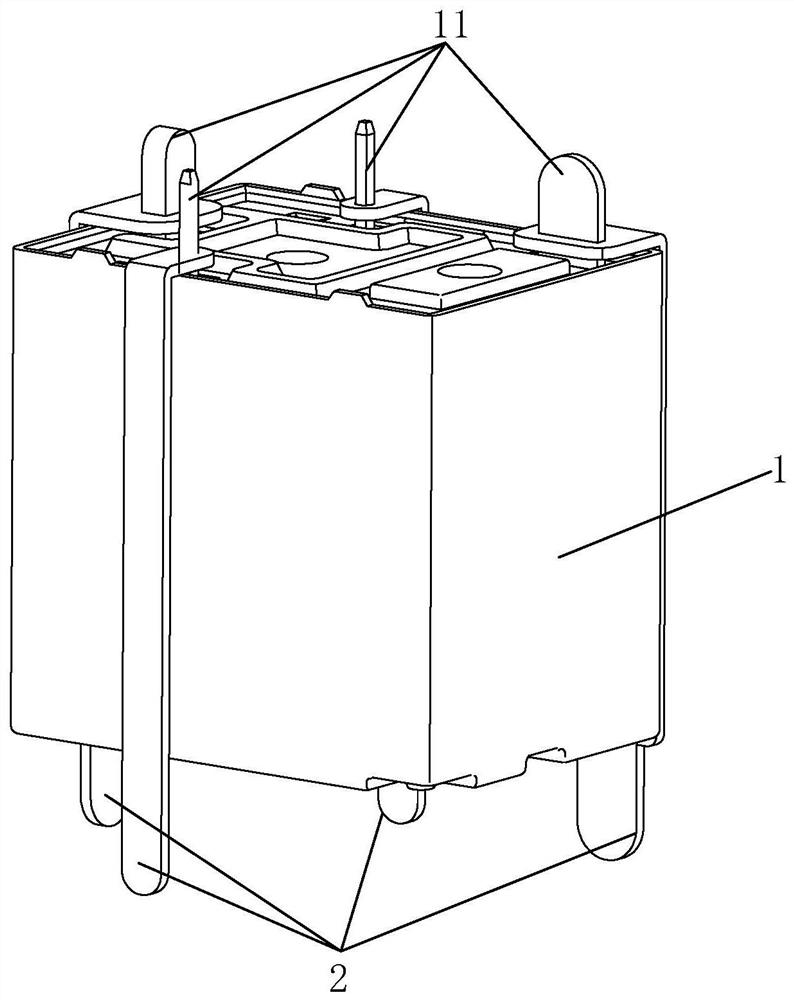
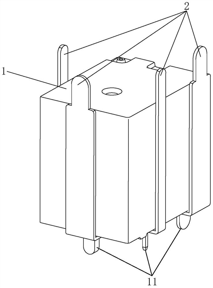
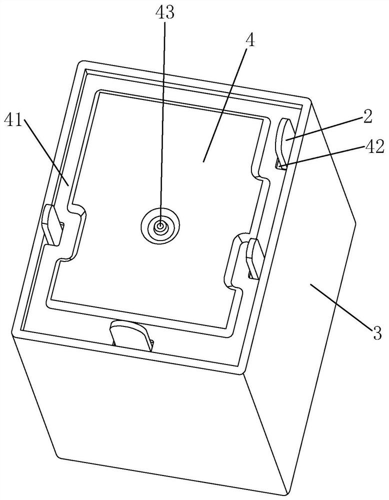
[0032] See Figure 1-Figure 5 As shown, a sealed relay of the present invention includes an electromagnetic relay 1 having several first lead-out pins 11 and a relay housing 12, and also includes a hollow sealed body and several second lead-out pins 2, the several second lead-out pins One end of 2 is electrically connected to several first lead-out pins 11 of the electromagnetic relay 1 respectively; the electromagnetic relay 1 and its first lead-out pins 11 are located in the sealing body, and the sealing body is filled with potting glue, and the potting glue Form at least the sealing layer 5 of each first lead-out pin 11 that wraps around the electromagnetic relay (that is, the part of each first lead-out pin 11 outside the relay housing 12 is in the sealing layer 5); the other end of each second lead-out pin 2 is located at Seal the outside of the body.

[0033] In this embodiment, the plurality of first lead-out pins 11 are located at the first end of the relay housing 12...

Embodiment 2

[0042] A hermetic relay of the present invention differs from the first embodiment above in that: the relay casing 12 is provided with a second vent hole (not shown in the figure), and the second vent hole is connected to the plurality of first lead-out holes. The pin 11 is located at the same end of the relay housing 12 (the second vent hole can be located at the base of the relay housing 12 or the position of the upper shell near the base), and is in the sealing layer 5. The second vent hole The hole is sealed before the electromagnetic relay enters the sealed body. In this way, it is ensured that the position of the second vent hole is always in the sealing layer 5, avoiding that the sealing layer 5 only forms a partial wrapping of the electromagnetic relay (such as Image 6 As shown), the second air hole is not protected by the sealing layer 5 (the second air hole of the traditional electromagnetic relay is generally located at the second end of the relay housing, that is,...


PUM


Abstract

The invention discloses a sealed relay, which comprises an electromagnetic relay with a plurality of first lead-out pins, and further comprises a hollow sealed body and a plurality of second lead-out pins, and one ends of the plurality of second lead-out pins are electrically connected with the plurality of first lead-out pins of the electromagnetic relay one by one respectively; the electromagnetic relay and the first leading-out pins of the electromagnetic relay are located in the sealing body, the sealing body is filled with pouring sealant, and the pouring sealant forms a sealing layer at least wrapping the first leading-out pins of the electromagnetic relay. The other end of each second lead-out pin is located outside the sealing body. A multi-sealing structure is adopted, so that the relay has high sealing performance and can be soaked and used in a liquid environment for a long time.

Description

technical field [0001] The invention relates to a relay, in particular to a sealed relay. Background technique [0002] With the rapid development of the Internet, the requirements for servers are getting higher and higher, and the power of servers is getting bigger and bigger, and the heat dissipation of servers has become a development bottleneck. At present, the heat dissipation method of servers in the computer room usually adopts an air-cooled cooling method. However, in large data centers, air cooling alone is not enough to meet the heat dissipation requirements of high heat flux density servers. Liquid cooling, that is, using the working fluid as the intermediate heat transfer medium to transfer heat from the hot zone to a distant place for cooling. Since the specific heat of liquid is much greater than that of air, and the heat dissipation speed is much faster than that of air, the cooling efficiency is much higher than that of air. Air-cooled heat dissipation, whi...

Claims


Application Information

Patent Timeline
Patent Type & Authority Applications(China)
IPC IPC(8): H01H50/02H01H50/14
CPCH01H50/023H01H50/14H01H50/041
Inventor 陈坤邓洋谭忠华朱艺青
Owner XIAMEN HONGFA ELECTROACOUSTIC CO LTD
Why Eureka
Try Eureka