Laser cleaning head

A laser cleaning and pulsed laser technology, applied in the field of laser cleaning head, can solve the problems of unsatisfactory cleaning effect, narrow cleaning range, spot surface cleaning method affecting laser cleaning efficiency, etc., and achieve simple structure, large cleaning range, increased The effect of large cleaning range

Active Publication Date: 2017-12-08
INST OF SEMICONDUCTORS - CHINESE ACAD OF SCI
View PDF4 Cites 10 Cited by
  • Summary
  • Abstract
  • Description
  • Claims
  • Application Information

AI Technical Summary

Problems solved by technology

With the continuous development of the market and the wide application, more and more enterprises and factories have begun to use this laser cleaning technology to replace the traditional cleaning technology. At this time, there is a fundamental problem that needs to be solved, that is, the efficiency of cleaning work. In the current laser cleaning system, the laser in the laser processing head passes through the laser reflector and then focuses through the focusing lens to act on the surface of the cleaned sample. Usually, the beam from the reflector forms a small spot after being focused, so that during laser cleaning Just form the speckled surface on the cleaning workpiece, because the cleaning range of the speckled surface is very narrow, and there will be small gaps in the connection between the speckled spots and spots during cleaning, which will make the overall cleaning effect not very ideal. The method will also affect the overall laser cleaning efficiency

Method used


Image

  • Laser cleaning head
  • Laser cleaning head

Examples


Embodiment

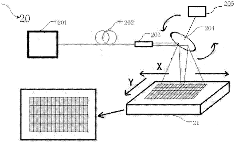
[0040] see figure 2 , the present embodiment proposes a high-efficiency laser cleaning processing head 20, including;

[0041] High-power pulsed laser 201, used to output pulsed high-power laser beam; the beam output power is 800W;

[0042] The energy transmission fiber 202 is used to transmit the high-power laser beam output by the high-power pulse laser to the tunable focusing beam reflector 204; the diameter of the fiber is 400 μm;

[0043] Laser collimator 203; used to perform beam shaping on the high-power laser beam output by the energy transmission fiber 202 to form a rectangular distributed beam;

[0044] Tunable focusing beam reflector 204; used to focus the high-power beam to form a linear beam, and simultaneously used to reflect the high-power laser beam to the surface of the laser cleaning sample 21, which is connected to the frequency adjustment device 205 to form a certain angle with the swing, the swing angle is between 36° and 58°.

[0045] Wherein the lase...


PUM


Abstract

A laser cleaning head comprises a pulse laser source, a transmitting energy fiber, a collimator and a reflector, wherein the pulse laser source is used for outputting a pulse laser beam; one end of the transmitting energy fiber is connected with the pulse laser source, and the transmitting energy fiber is used for transmitting the pulse laser beam; the collimator is connected with the other end of the transmitting energy fiber and used for collimating the pulse laser beam; the reflector is used for emitting the pulse laser beam to the surface of a cleaned sample piece. Thus, the laser cleaning head is simple in structure and convenient to operate. A tunable focusing light beam reflector is used as the reflector and can conduct focusing shaping on the light beam while reflecting the laser light beam. The emitted light beam can become a high-power rectangular light beam. Accordingly, the light beam emitted onto the surface of a cleaned article is a line beam, and a line spot surface. Thus, the cleaning range is large. Tiny gaps occur when points and spots are connected in a traditional cleaning mode are avoided. The overall cleaning effect is improved.

Description

technical field [0001] The invention belongs to the field of laser cleaning, and more specifically relates to a laser cleaning head. Background technique [0002] Laser cleaning is an efficient and green cleaning technology. Compared with chemical cleaning and mechanical cleaning, laser cleaning has certain advantages. It does not require any chemical reagents, no grinding, no stress, no consumables, less damage to the substrate, and high cleanliness. . The laser is guided by optical fiber transmission, which can clean parts that are difficult to reach, and has a wide range of applications, such as rust removal, paint removal, mud removal, and wafer surface treatment. This technology has been gradually applied in various fields. With the continuous development of the market and the wide application, more and more enterprises and factories have begun to use this laser cleaning technology to replace the traditional cleaning technology. At this time, there is a fundamental pr...

Claims


Application Information

Patent Timeline
Patent Type & Authority Applications(China)
IPC IPC(8): B08B7/00G02B27/09
CPCB08B7/0042G02B27/0977G02B27/0994
Inventor 张志研林学春梁浩王奕博刘燕楠马文浩
Owner INST OF SEMICONDUCTORS - CHINESE ACAD OF SCI
Why Eureka
Try Eureka