Material box cleaning equipment for food safety production

A technology for cleaning equipment and food safety, applied in the direction of cleaning hollow objects, cleaning methods and utensils, chemical instruments and methods, etc., to achieve the effect of increasing the stabilization effect

Pending Publication Date: 2021-10-29
刘萍
View PDF0 Cites 0 Cited by
  • Summary
  • Abstract
  • Description
  • Claims
  • Application Information

AI Technical Summary

Problems solved by technology

[0004] In order to solve the above technical problems, the present invention provides a bin cleaning equipment for food safety production to solve the existing problems

Method used


Image

  • Material box cleaning equipment for food safety production
  • Material box cleaning equipment for food safety production
  • Material box cleaning equipment for food safety production

Examples


Embodiment 1

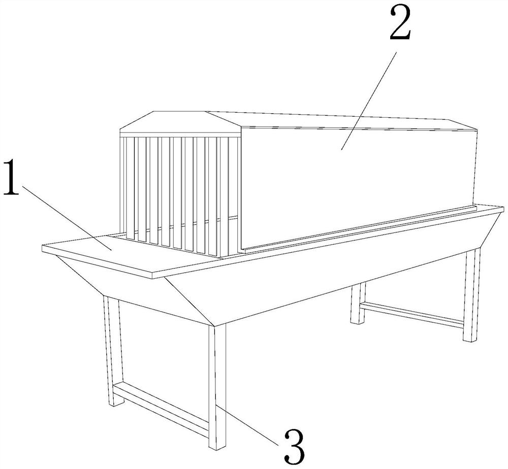
[0030] as attached figure 1 to attach Figure 6 Shown:

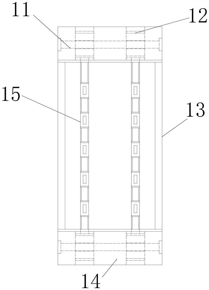
[0031] The present invention provides a material box cleaning equipment for food safety production, the structure of which includes a transmission device 1, a cleaning box 2, and a support rod 3, the upper end of the transmission device 1 is welded to the lower end of the cleaning box 2, and the support rod 3 The upper end is welded to the lower end of the transmission device 1. The transmission device 1 includes a mounting rod 11, a transmission plate 12, a mounting plate 13, a storage plate 14, and a transmission chain plate 15. The outside of the installation rod 11 is movably engaged with the inside of the transmission plate 12. The outer sides of both ends of the installation rod 11 are embedded and connected with the inner side of the storage plate 14, the inner side of the transmission plate 12 is movably engaged with the outer side of the transmission chain plate 15, and the outer side of the installation plate...

Embodiment 2

[0039] as attached Figure 7 to attach Figure 9 Shown:

[0040] The present invention provides a bin cleaning device for food safety production. The auxiliary plate 531 includes a reinforcement plate 311, an anti-skid plate 312, and a pressure block 313. The right end of the reinforcement plate 311 is embedded and connected to the left end of the anti-skid plate 312. The left end of the pressure block 313 is vertically installed on the right end of the reinforcement plate 311. There are two anti-skid plates 312, distributed and installed on both sides of the pressure block 313, and made of rough plastic material, so that the auxiliary plate 531 can rotate At this time, the friction force with the material frame is increased through the material and quantity properties of the anti-skid plate 312, so as to play an anti-skid effect.

[0041] Wherein, the pressure block 313 includes a pressure receiving plate 131, a connecting block 132, an embedding plate 133, and a pressure s...


PUM


Abstract

The invention provides material box cleaning equipment for food safety production. The material box cleaning equipment structurally includes a conveying device, a cleaning box and a supporting rod; the upper end of the conveying device is welded to the lower end of the cleaning box; the upper end of the supporting rod is welded to the lower end of the conveying device; the conveying device comprises a mounting rod, a transmission disc, a mounting plate, a storage plate and a transmission chain plate; the outer side of the mounting rod is movably clamped to the inner side of the transmission disc; the outer sides of the two ends of the mounting rod are fixedly connected with the inner side of the storage plate in an embedded mode; and the inner side of the transmission disc is movably clamped to the outer side of the transmission chain plate. A frame is forcibly pressed on a reinforcing device, so that anti-skid strips press a connecting plate at the lower end, extrusion blocks at the bottom deform and push a movable protruding block at the right end, friction force can be increased through anti-skid protruding blocks on a fixed plate and an auxiliary top plate, and therefore the right end of the movable protruding block and a movable plate are clamped, and the outer side of the frame is fixed through an auxiliary plate.

Description

technical field [0001] The invention belongs to the field of food safety production, and more specifically relates to a bin cleaning device for food safety production. Background technique [0002] The material box is mainly used to place the processed food. Some of the produced food will form dirt on the inner wall of the material box. The material box is mainly designed in a grid shape, which is convenient for cleaning, ventilation and drying of the material box. Place the material frame on the conveyor belt of the washing machine for transportation. When the material frame is transported to the inside of the cleaning box, the material frame is sprayed by the internal high-pressure water gun to achieve the cleaning effect. [0003] When the material frame is placed on the conveying chain and enters the cleaning box, in order to increase the cleaning effect of the material frame, there are many high-pressure water guns installed inside the cleaning box, and they are install...

Claims


Application Information

Patent Timeline
IPC IPC(8): B08B9/30B08B9/42
CPCB08B9/30B08B9/42
Inventor 刘萍
Owner 刘萍
Why Eureka
Try Eureka