Emergency speed reduction system of unmanned aerial vehicle, working method thereof and unmanned aerial vehicle

An unmanned aerial vehicle (UAV), an emergency technology, applied to unmanned aerial vehicles, affecting the air flow over the surface of the aircraft, motor vehicles, etc. High controllability and good control linearity

Pending Publication Date: 2021-10-29
广东佰沃科技有限公司
View PDF0 Cites 0 Cited by
  • Summary
  • Abstract
  • Description
  • Claims
  • Application Information

AI Technical Summary

Problems solved by technology

[0003] At present, the rotor UAV can achieve the effect of emergency deceleration to achieve braking, while the fixed-wing UAV does not have a more mature function of emergency deceleration to achieve braking. Therefore, it is necessary to provide a fixed-wing UAV that can be used Man-machine emergency deceleration system to improve the maneuverability and flexibility of fixed-wing drones

Method used


Image

  • Emergency speed reduction system of unmanned aerial vehicle, working method thereof and unmanned aerial vehicle
  • Emergency speed reduction system of unmanned aerial vehicle, working method thereof and unmanned aerial vehicle
  • Emergency speed reduction system of unmanned aerial vehicle, working method thereof and unmanned aerial vehicle

Examples


Embodiment 1

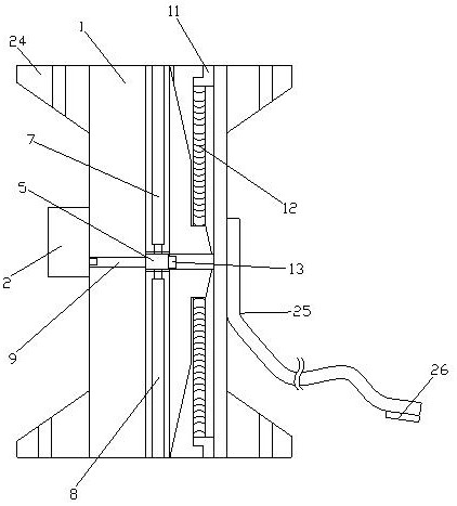
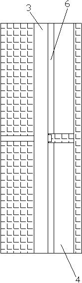
[0032] Such as Figure 1-4As shown, an emergency deceleration system for a UAV, including a UAV master control (not shown) and a wind resistance generating device perpendicular to the ground and placed in the UAV, the wind resistance generating device includes a connection Seat 1 and steering gear 2, the connecting seat 1 is provided with a first storage tank 3, a second storage tank 4 and a shaft hole (not shown), between the first storage tank 3 and the second storage tank 4 A guide hole 6 is provided, and the first storage tank 3 and the second storage tank 4 are connected through the guide hole 6. An upper wind resistance plate 7 and a lower wind resistance plate 8 are arranged in the first storage tank 3, and the upper wind resistance plate A transmission plate 5 is arranged between the plate 7 and the lower air resistance plate 8, and a connecting shaft 9 is inserted in the shaft hole, one end of the connecting shaft 9 is fixedly connected with the transmission plate 5, ...

Embodiment 2

[0034] Such as Figure 1-4 As shown, an emergency deceleration system for a UAV, including a UAV master control (not shown) and a wind resistance generating device perpendicular to the ground and placed in the UAV, the wind resistance generating device includes a connection Seat 1 and steering gear 2, the connecting seat 1 is provided with a first storage tank 3, a second storage tank 4 and a shaft hole (not shown), between the first storage tank 3 and the second storage tank 4 A guide hole 6 is provided, and the first storage tank 3 and the second storage tank 4 are connected through the guide hole 6. An upper wind resistance plate 7 and a lower wind resistance plate 8 are arranged in the first storage tank 3, and the upper wind resistance plate A transmission plate 5 is arranged between the plate 7 and the lower air resistance plate 8, and a connecting shaft 9 is inserted in the shaft hole, one end of the connecting shaft 9 is fixedly connected with the transmission plate 5,...


PUM


Abstract

The invention discloses an emergency speed reduction system of an unmanned aerial vehicle, a working method of the emergency speed reduction system and the unmanned aerial vehicle. The emergency speed reduction system comprises a wind resistance generating device, the wind resistance generating device comprises a connecting base and a steering engine, and the connecting base is provided with a first storage groove, a second storage groove and a shaft hole; a guide hole is formed between the first storage groove and the second storage groove, an upper wind resistance plate and a lower wind resistance plate are arranged in the first storage groove, a transmission plate is arranged between the upper wind resistance plate and the lower wind resistance plate, a connecting shaft is inserted into the shaft hole, reinforcing plates are arranged on the back face of the upper wind resistance plate and the back face of the lower wind resistance plate, and the reinforcing plates penetrate through the guide hole; and an L-shaped connecting piece is arranged in the second storage groove, a mounting groove is formed in the reinforcing plate, and a first reset spring is arranged between the back face of the L-shaped connecting piece and the groove bottom of the mounting groove. The emergency speed reduction system of the unmanned aerial vehicle has the advantages that the overall wind resistance of the unmanned aerial vehicle can be continuously increased by the emergency speed reduction system of the unmanned aerial vehicle through control, accordingly, speed reduction can be realized, and the effect similar to braking can be achieved.

Description

technical field [0001] The invention relates to an emergency deceleration system of an unmanned aerial vehicle, its working method and an unmanned aerial vehicle. Background technique [0002] UAVs have the great advantages of being able to adapt to complex and harsh environments, not requiring personnel to drive, and not causing personnel losses, so they have been used more and more widely. At present, UAV technology is used in remote sensing measurement and control, aerial photography surveying and mapping, environmental reconnaissance and other fields. With the increase of applications, UAV technology is getting hotter and hotter, and the types of UAVs tend to be diversified. Among them, fixed-wing UAVs occupy a large proportion in the field of UAVs. Fixed-wing UAVs have the advantages of long flight distance, large range, stable flight, and safety. [0003] At present, the rotor UAV can achieve the effect of emergency deceleration to achieve braking, while the fixed-wi...

Claims


Application Information

Patent Timeline
Patent Type & Authority Applications(China)
IPC IPC(8): B64C21/00B64C13/50B64D27/24H01M10/613H01M10/653
CPCB64C21/00B64C13/50B64D27/24H01M10/613H01M10/653B64U50/19Y02E60/10Y02T50/60
Inventor 黄楠铭陈赋明
Owner 广东佰沃科技有限公司
Why Eureka
Try Eureka