
Hearth welding flaw detection device and method for soot blower

A flaw detection device and soot blower technology, applied in combustion methods, measuring devices, instruments, etc., can solve problems such as troublesome operation and affect the effect of flaw detection, so as to improve the stability, improve the effect of flaw detection, and facilitate segmented Detecting the effect of information collection

Active Publication Date: 2021-10-29
浙江莱梦德电力设备有限公司
View PDF16 Cites 0 Cited by
  • Summary
  • Abstract
  • Description
  • Claims
  • Application Information

AI Technical Summary

Problems solved by technology

[0003] However, most of the existing furnace welding flaw detection devices have relatively simple structures. When performing flaw detection on the welded part of the inner wall of the furnace tube, the flaw detector needs to be transported to the furnace tube, and the flaw detector needs to be manually rotated to adjust the position of the flaw detector. It is troublesome to perform flaw detection on the furnace tube, and if debris appears in the welding part, it will easily affect the effect of flaw detection if there is no effective cleaning. Therefore, we propose a furnace welding flaw detection device for soot blowers and method to solve the above problems

Method used


Image

  • Hearth welding flaw detection device and method for soot blower
  • Hearth welding flaw detection device and method for soot blower
  • Hearth welding flaw detection device and method for soot blower

Examples


Embodiment

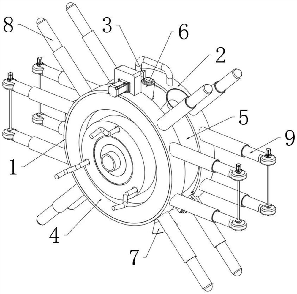
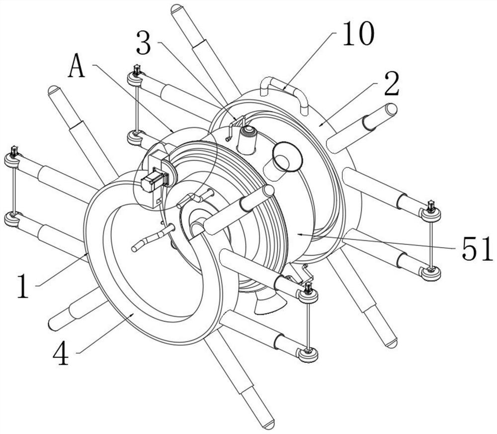
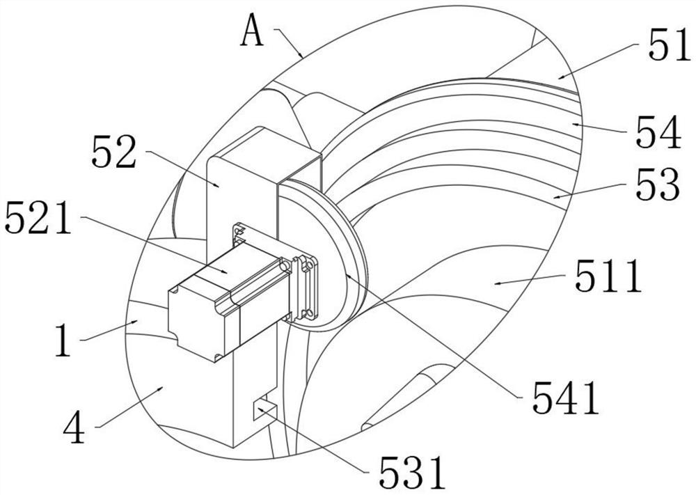
[0039] Example: such as Figure 1-9 As shown, the present invention provides a technical solution: a furnace welding flaw detection device for a soot blower, comprising a first frame 1 and a second frame 2, the first frame 1 and the second frame 2 have the same structure And the horizontal corresponding distribution, between the first frame 1 and the second frame 2 is fixedly installed with the connection assembly 3, the connection assembly 3 is provided with multiple groups distributed in a circular array; the first frame 1 and the second frame 2 The opposite ends are fixed with a card frame 4, and a drive mechanism 5 is provided between the two sets of card frames 4. The drive mechanism 5 is equipped with a flaw detector 6 and a cleaning component 7. The first set of frames 1 and the second set of frames 2 The outer walls of the outer walls are fixedly equipped with guide assemblies 8, and the guide assemblies 8 are provided with four groups distributed in a circular array; ...


PUM


Abstract

The invention discloses a hearth welding flaw detection device and method for a soot blower, and belongs to the technical field of hearth welding. The hearth welding flaw detection device comprises a first sleeve frame and a second sleeve frame, wherein the first sleeve frame and the second sleeve frame have the same structure and are horizontally and correspondingly distributed, a connecting assembly is fixedly mounted between the first sleeve frame and the second sleeve frame, clamping frames are fixedly arranged at the opposite ends of the first sleeve frame and the second sleeve frame in a clamped mode, a driving mechanism is arranged between the two clamping frames, a flaw detector and a cleaning assembly are arranged in the driving mechanism, guiding assemblies are fixedly installed on the outer walls of the first sleeve frame and the second sleeve frame, and moving assemblies are fixedly mounted on the outer walls of the first sleeve frame and the second sleeve frame. According to the flaw detection device, a cleaning assembly is arranged at the position adjacent to the flaw detector, debris cleaning can be carried out on a welding part before flaw detection is carried out on the welding part, therefore the debris is prevented from influencing flaw detection on the welding part, and the flaw detection effect of the whole device is improved.

Description

technical field [0001] The invention relates to the technical field of furnace welding, in particular to a furnace welding flaw detection device and method for a sootblower. Background technique [0002] Soot blower is a device used to remove soot on the heating surface of the boiler. It is usually composed of soot blowing pipes and operating valves. It is often used in industrial boilers and is generally installed in the boiler furnace, horizontal flue and tail flue, etc. The furnace wall of the sootblower needs to be welded to the furnace wall of the sootblower when it is used. After welding, it is necessary to perform flaw detection on the welded part of the furnace to prevent the water-cooled wall from bursting when the sootblower is used. [0003] However, most of the existing furnace welding flaw detection devices have relatively simple structures. When performing flaw detection on the welded part of the inner wall of the furnace tube, the flaw detector needs to be tra...

Claims


Application Information

Patent Timeline
Patent Type & Authority Applications(China)
IPC IPC(8): F23J3/02F23J1/00G01N33/00B62D57/024
CPCF23J3/02F23J1/00G01N33/00B62D57/024F23J2700/001
Inventor 姜建勇张莹蒋旭初傅伟平
Owner 浙江莱梦德电力设备有限公司
Learn More