Steering difference correction method for vector magnetic gradiometer

A magnetic gradiometer and calibration method technology, applied in instruments, measuring devices, measuring electrical variables, etc., can solve problems such as the magnetic gradient error correction method not mentioned, and achieve the effects of versatility, simple calculation, and simple operation.

Pending Publication Date: 2021-10-29
THE 715TH RES INST OF CHINA SHIPBUILDING IND CORP
View PDF4 Cites 2 Cited by
  • Summary
  • Abstract
  • Description
  • Claims
  • Application Information

AI Technical Summary

Problems solved by technology

The method does not mention the error correction method of the magnetic gradient

Method used


Image

  • Steering difference correction method for vector magnetic gradiometer
  • Steering difference correction method for vector magnetic gradiometer
  • Steering difference correction method for vector magnetic gradiometer

Examples


Embodiment Construction

[0049] The present invention will be described in detail below with reference to the accompanying drawings: the specific implementation includes two parts: the implementation of correction model parameter acquisition; the implementation of attitude error correction.

[0050] The implementation method of obtaining calibration model parameters includes the following steps:

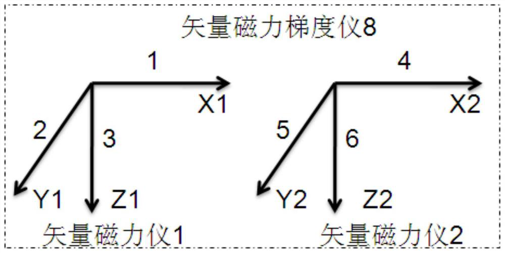
[0051] The schematic diagram of the internal components of the vector magnetic gradiometer (8) is as follows: figure 1 As shown, there are two sets of vector magnetometers inside: vector magnetometer 1 and vector magnetometer 2, both of which are rigidly fixed, where the X1 axis (1) of vector magnetometer 1 and the X2 axis (4) of vector magnetometer 2 are arranged on In the same direction, the Y1 axis (2) of the vector magnetometer 1 and the Y2 axis (5) of the vector magnetometer 2 are arranged in the same direction, and the Z1 axis (3) of the vector magnetometer 1 and the Z2 axis ( 6) Arranged in the same ...


PUM


Abstract

The invention relates to a steering difference correction method for a vector magnetic gradiometer. The method is suitable for component gradient error correction of a magnetic gradiometer composed of two sets of vector magnetometers, and comprises the following steps of: establishing a gradient error correction model, introducing a three-axis non-magnetic reference turntable to carry out accurate attitude rotation, separating and solving a single model parameter according to standard attitude transformation, and completing parameter calculation in the error correction model one by one so as to avoid complex and tedious matrix operation; and introducing an attitude heading sensor to obtain three kinds of angle information of the vector magnetic gradiometer, and solving attitude error correction parameters through a relational expression between residual gradient errors of all components and angle data. After the correction process is completed, the gradient error of each component is reduced to + / -4.0 nT from the maximum + / -380.0 nT, the correction error is reduced by 98.95%, and the output steering difference of the vector magnetic gradiometer is greatly reduced.

Description

technical field [0001] The invention belongs to the field of magnetic sensor error correction, and mainly relates to a steering difference correction method of a vector magnetic gradiometer. Background technique [0002] The vector magnetometer is composed of three two-by-two vertical magnetic component sensors, which respectively measure the geomagnetic component of the geomagnetic field in its axial direction. The three-component magnetic field can be calculated according to the three-dimensional coordinate axis to obtain the combined total field value. Therefore, the magnetic field measured by the vector magnetometer Values ​​include the magnitude and direction of the components, and the magnitude of the total field value. The magnetic field measured by the scalar magnetometer is the total geomagnetic field, which has only magnitude but no direction. Therefore, compared with the scalar magnetometer, the measured information of the vector magnetometer is more comprehensive...

Claims


Application Information

Patent Timeline
Patent Type & Authority Applications(China)
IPC IPC(8): G01R35/00
CPCG01R35/005
Inventor 赵瑜周波朱文兵周建斐綦俊峰刘雨聪蒋弘威
Owner THE 715TH RES INST OF CHINA SHIPBUILDING IND CORP
Why Eureka
Try Eureka