Control method and system for inhibiting magnetizing inrush current of train traction transformer and train
A traction transformer and excitation inrush current technology, applied in electrical components, emergency protection circuit devices, etc., can solve problems such as traction transformer oversaturation, high-speed train impact, relay malfunction, etc., to eliminate excitation inrush current, reduce hazards, and reduce malfunctions Effect
- Summary
- Abstract
- Description
- Claims
- Application Information
AI Technical Summary
Problems solved by technology
Method used
Image

Examples
Embodiment 1
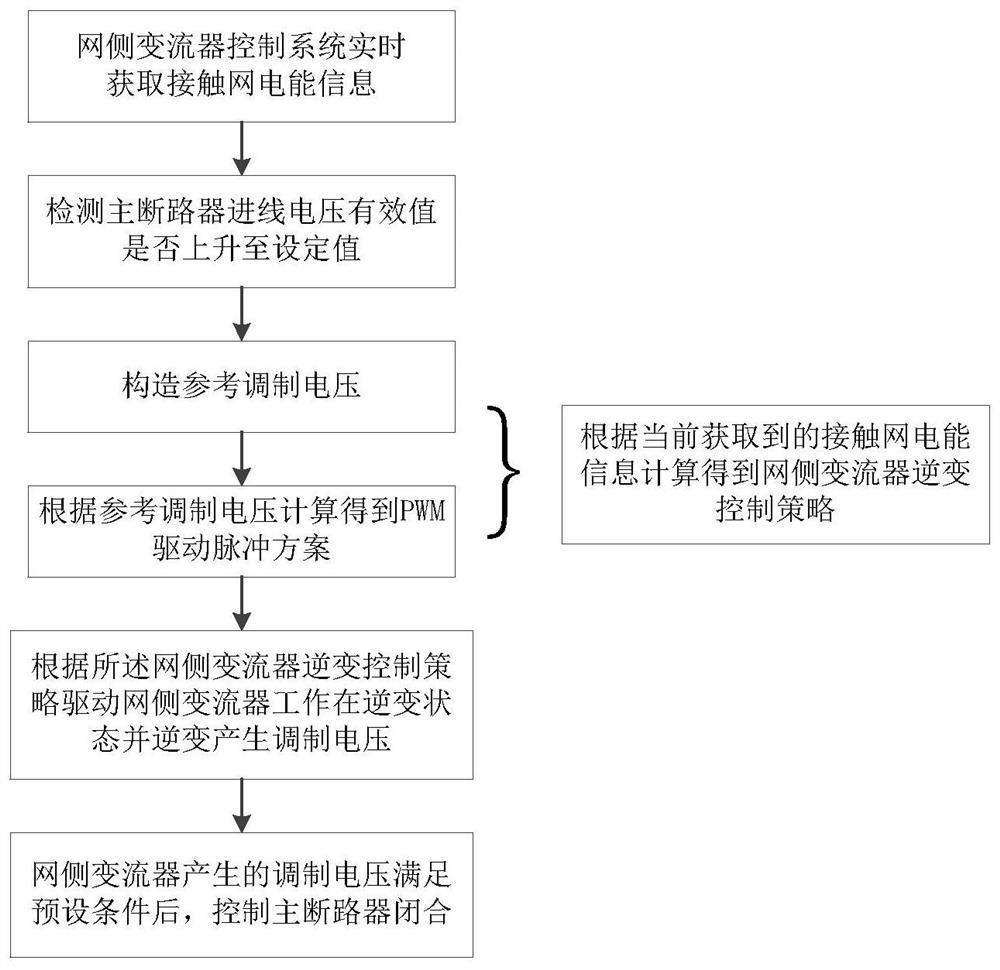
[0042] Such as figure 1 As shown, this embodiment provides a control method for suppressing the inrush current of a train traction transformer, including:
[0043] The control system of the grid-side converter obtains the power information of the catenary in real time;
[0044] Detect whether the effective value of the incoming line voltage of the main circuit breaker has risen to the set value, and if so, calculate the inverter control strategy of the grid-side converter according to the currently obtained catenary power information;
[0045] Drive the grid-side converter to work in the inverter state according to the inverter control strategy of the grid-side converter, and invert to generate a modulation voltage;
[0046] After the modulation voltage generated by the grid-side converter meets the preset conditions, the main circuit breaker is controlled to be closed.
[0047] What needs to be explained here is that when the train is over-phased, the main circuit breaker w...
Embodiment 2
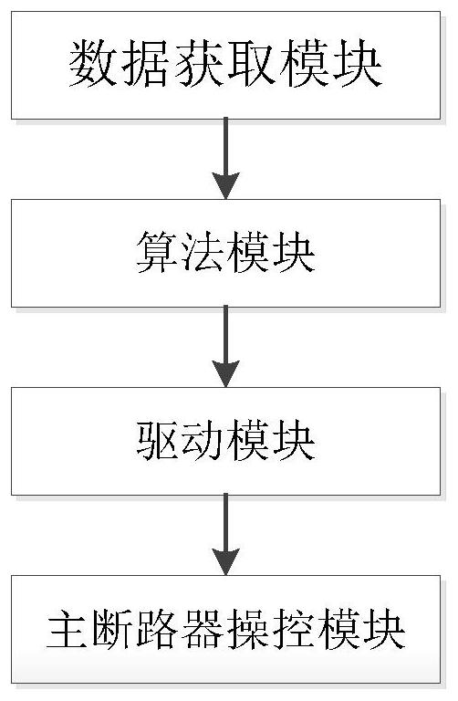
[0060] Such as figure 2 As shown, the present embodiment provides a control system for suppressing the inrush current of the train traction transformer, including:
[0061] Data acquisition module: used to acquire catenary power information in real time;
[0062] Algorithm module: used to detect whether the incoming line voltage of the main circuit breaker has risen to the set value, and if so, calculate and obtain the inverter control strategy of the grid-side converter according to the currently obtained catenary power information;
[0063] Drive module: used to drive the grid-side converter to work in the inverter state according to the inverter control strategy of the grid-side converter, and the inverter generates a modulation voltage;
[0064] Main circuit breaker control module: used to control the closing of the main circuit breaker after the modulation voltage generated by the grid-side converter meets the preset conditions.
[0065] Preferably, the algorithm modul...
Embodiment 3
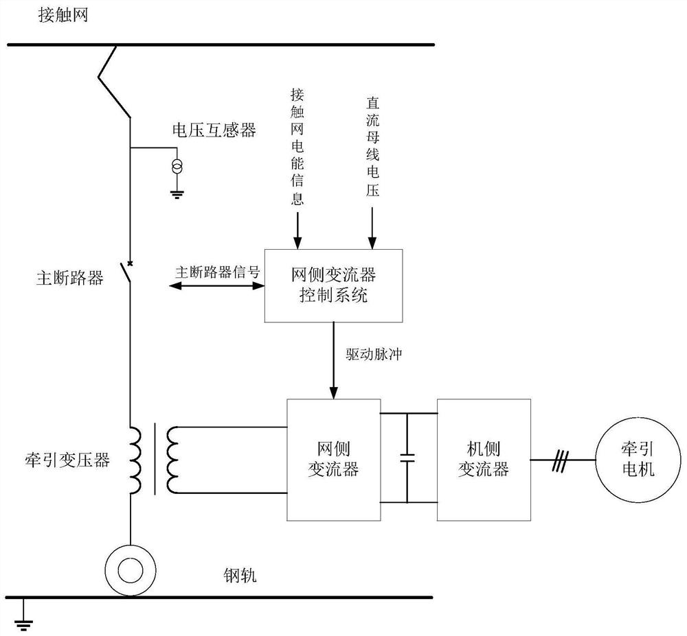
[0072] Such as image 3 As shown, this embodiment provides a train traction drive system, including a traction transformer whose primary side is connected to the catenary through a main circuit breaker, the secondary side of the traction transformer is connected to the AC terminal of the grid-side converter, and the grid-side converter The DC terminal is connected to the DC terminal of the machine-side converter through the DC bus, and the AC terminal of the machine-side converter is connected to the train traction motor. The train traction drive system also includes the control system as described in Embodiment 2.
PUM
 Abstract
Description
Claims
Application Information
 - Generate Ideas
- Intellectual Property
- Life Sciences
- Materials
- Tech Scout
- Unparalleled Data Quality
- Higher Quality Content
- 60% Fewer Hallucinations
Browse by: Latest US Patents, China's latest patents, Technical Efficacy Thesaurus, Application Domain, Technology Topic, Popular Technical Reports.
© 2025 PatSnap. All rights reserved.Legal|Privacy policy|Modern Slavery Act Transparency Statement|Sitemap|About US| Contact US: help@patsnap.com