
Mopping robot workstation and mop humidity control method

A mopping robot and humidity control technology, applied in robot cleaning machines, machine parts, carpet cleaning, etc., can solve the problems of affecting the mopping effect, reducing the mopping effect, and inapplicability, and achieving the effect of improving the mopping effect.

Active Publication Date: 2021-11-02
海尔机器人科技(青岛)有限公司 +1
View PDF18 Cites 1 Cited by
  • Summary
  • Abstract
  • Description
  • Claims
  • Application Information

AI Technical Summary

Problems solved by technology

[0004] But regardless of the cleaning method, the mop has the problem of wringing out the mop. In the case of manual cleaning, the user needs to wring it out with both hands, which increases the burden on the user; in the way of cleaning the mop by the mopping robot, it is generally necessary to design a scraper or squeeze Pressing and other wringing structures, through which the water is squeezed out of the mop to realize the wringing of the mop
[0005] In practical applications, the humidity of the mop directly affects the mopping effect due to factors such as the degree of dirtiness of the user's indoor floor, floor material, and user needs. If the ground is relatively clean but the mop is wet, the moisture content on the ground will be too high It is not easy to dry. If the ground is dirty but the mop is too dry, the mopping effect will be reduced; however, the manual wring method is affected by the strength of the user, and there is uncertainty in the humidity of the mop, and the structure of the mopping robot itself wrings out the mop. The degree is relatively fixed. These situations are not universal and cannot be applied to different ground conditions, thus affecting the mopping effect.

Method used


Image

  • Mopping robot workstation and mop humidity control method
  • Mopping robot workstation and mop humidity control method
  • Mopping robot workstation and mop humidity control method

Examples


Embodiment Construction

[0035] The specific implementation manners of the present invention will be further described in detail below in conjunction with the accompanying drawings.

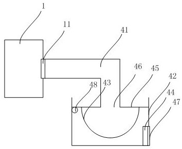
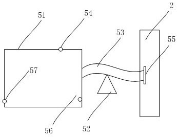
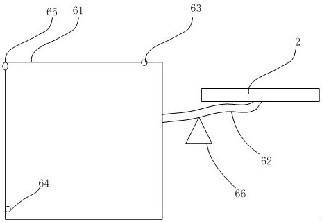
[0036] Such as Figure 14 As shown, the mopping machine workbench proposed by the present invention includes: mopping machine workbench 2, cleaning device 201, dehydration device 202, mop humidity determination module 203, dehydration device execution time determination module 204 and mop humidity control module 205.

[0037] The mopping machine workbench 2 is responsible for charging the mopping robot; the cleaning device 201 is connected to the mopping machine workbench 2 for wetting the mop of the mopping robot; There are several protrusions; the mop humidity determination module 203 is used to obtain the humidity level set by the user; the dehydration device execution time determination module 204 is used to determine the execution time of the dehydration device based on the humidity level set by the user; the mop hu...


PUM


Abstract

The invention discloses a mopping robot workbench and a mop humidity control method. The mopping robot workbench comprises a mopping machine workbench, a cleaning device, a dewatering device, a mop humidity determination module, a dewatering device execution time determination module and a mop humidity control module. A user can set the humidity of the mop cloth according to the ground smudginess degree, the ground material or user requirements, the mopping robot workstation determines the execution duration of the dewatering device based on the humidity gear set by the user, after the mop cloth is wetted, the dewatering device is controlled to be started, water and dust are squeezed out of the mop cloth based on a plurality of protrusions on the surface of the dewatering device, and different execution durations correspond to different humidity so that the humidity of the mopping cloth is suitable for different ground conditions, and the mopping effect of the mopping robot is improved.

Description

technical field [0001] The invention belongs to the technical field of household cleaning, and in particular relates to a floor mopping robot workstation and a mop humidity control method. Background technique [0002] The mopping robot can realize automatic cleaning at home and reduce the burden of household chores for users, but at the same time there is also the problem of mop cleaning. [0003] In the prior art, the mop cleaning of the mopping robot is either manually removed by the user, and then installed and used after cleaning, or the mopping robot itself carries a water tank and a mop cleaning structure to realize automatic cleaning. [0004] But regardless of the cleaning method, the mop has the problem of wringing out the mop. In the case of manual cleaning, the user needs to wring it out with both hands, which increases the burden on the user; in the way of cleaning the mop by the mopping robot, it is generally necessary to design a scraper or squeeze Pressing a...

Claims


Application Information

Patent Timeline
IPC IPC(8): A47L11/282A47L11/284A47L11/40
CPCA47L11/282A47L11/284A47L11/40A47L11/4011A47L11/4091A47L2201/02A47L2201/022A47L2201/00
Inventor 徐华鲜策孙磊白宏磊
Owner 海尔机器人科技(青岛)有限公司
Learn More