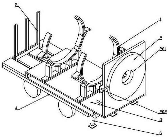
Transfer device for wind power generation flexible tower

A transfer device, flexible tower technology, applied in transportation and packaging, vehicles for freight, vehicles for carrying long goods, etc. The problem of slow locking speed, etc., achieves the effect of facilitating the installation of the flexible tower, improving the hoisting efficiency and transporting safety.

Active Publication Date: 2021-11-02
SINOHYDRO BUREAU 4 JIUQUAN NEW ENERGY EQUIPCO
View PDF6 Cites 3 Cited by
  • Summary
  • Abstract
  • Description
  • Claims
  • Application Information

AI Technical Summary

Problems solved by technology

In recent years, the focus of my country's wind power development has gradually shifted to areas with low wind speeds. Therefore, the application of soft towers is more common. The existing soft tower transportation still uses conventional transfer devices, which cannot meet the needs of soft tower transfer speeds.
[0003] The existing flexible tower transfer device needs to lift the flexible tower to the transfer vehicle, and then lock the flexible tower on the vehicle through the transfer device. The vehicle transports the flexible tower to the installation position, and then releases the locking of the flexible tower by the transfer device. , the lifting device will lift the flexible tower horizontally to the placement position, and then lift the flexible tower into a vertical state again. The conventional transfer device will cause the flexible tower to lock slowly. The installation of flexible towers slows down the transfer speed, increases the lifting steps, and reduces the installation efficiency of flexible towers. Therefore, we propose a transfer device for wind power flexible towers

Method used


Image

  • Transfer device for wind power generation flexible tower
  • Transfer device for wind power generation flexible tower
  • Transfer device for wind power generation flexible tower

Examples


Embodiment Construction

[0024] The technical solution of this patent will be further described in detail below in conjunction with specific embodiments.

[0025] Embodiments of the present patent are described in detail below, examples of which are shown in the drawings, wherein the same or similar reference numerals designate the same or similar elements or elements having the same or similar functions throughout. The embodiments described below by referring to the figures are exemplary and are only used for explaining the patent, and should not be construed as limiting the patent.

[0026] In the description of this patent, it is to be understood that the terms "center", "upper", "lower", "front", "rear", "left", "right", "vertical", "horizontal", The orientation or positional relationship indicated by "top", "bottom", "inner", "outer", etc. is based on the orientation or positional relationship shown in the drawings, and is only for the convenience of describing this patent and simplifying the des...


PUM


Abstract

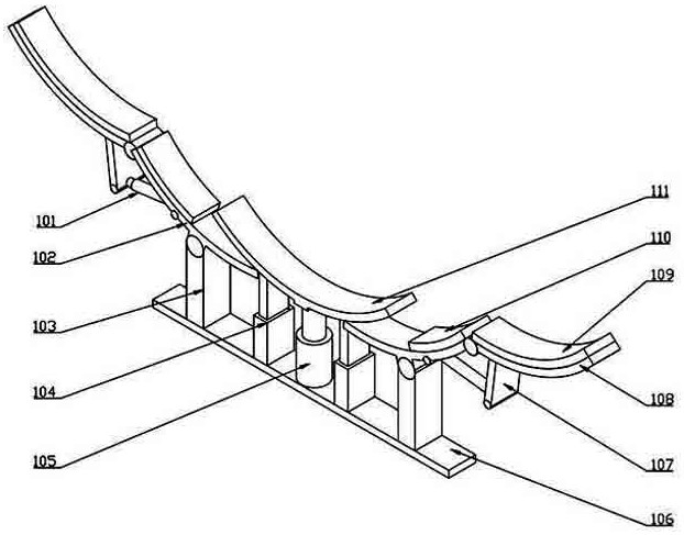
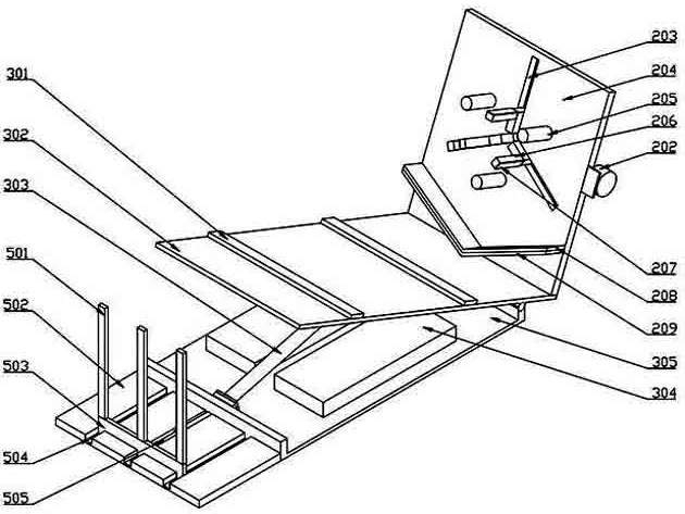
The invention provides a transfer device for a wind power generation flexible tower, belongs to the technical field of wind power equipment transportation, and is used for solving the problem that an existing transfer device is inconvenient to transport, lock, hoist and transfer a flexible tower. The device comprises a rotating mechanism and two locking mechanisms, the rotating mechanism comprises a bottom plate, an extrusion mechanism is arranged on the side face of the bottom plate, a rotating plate is hinged to the bottom plate, an anti-falling mechanism is arranged on the rotating plate, each locking mechanism comprises a fixing plate, a first hydraulic cylinder and two sleeve rods are fixed to the fixing plate, lifting arc plates are fixed to the first hydraulic cylinders and the sleeve rods, two supporting columns are fixed to the upper portion of the fixing plate, a first rotating arc plate is hinged to the supporting columns, an electric push rod is hinged to the lower portion of the first rotating arc plate, a second rotating arc plate is hinged to the end of the first rotating arc plate, a connecting plate is fixed to the lower portion of the second rotating arc plate, and the connecting plate is hinged to the end of the electric push rod. The flexible tower can be conveniently transported, locked, hoisted and transferred.

Description

technical field [0001] The invention belongs to the technical field of wind power equipment transportation, and relates to a transfer device for a wind power generation flexible tower. Background technique [0002] The flexible tower is a kind of wind power tower. The "softness" of the flexible tower is related to the rated speed of the impeller. The first-order frequency at the rated speed of the impeller is called 1P, and the third-order frequency is called 3p; when the frequency of the tower itself The one above the first-order frequency of the impeller is a traditional tower, and the one below 1P is a soft tower. In recent years, the focus of my country's wind power development has gradually shifted to areas with low wind speeds. Therefore, the application of soft towers is more common. The existing soft tower transportation still uses conventional transfer devices, which cannot meet the needs of soft tower transfer speeds. [0003] The existing flexible tower transfer ...

Claims


Application Information

Patent Timeline
Patent Type & Authority Applications(China)
IPC IPC(8): B60P3/40B60P7/135B60P7/16B66C13/08
CPCB60P3/40B60P7/135B60P7/16B66C13/08
Inventor 郭平俊刘华云刘世彦管伟陈琨谢全德吴双张晶韩永倩高金芳
Owner SINOHYDRO BUREAU 4 JIUQUAN NEW ENERGY EQUIPCO
Why Eureka
Try Eureka