
Water-carrying floating-reducing and floating-resisting system and basement structure

A basement and drainage system technology, applied in the direction of infrastructure engineering, building construction, protection devices, etc., can solve the problems of not exerting the self-weight of the building, high drainage costs, and high requirements for drainage components

Pending Publication Date: 2021-11-02
广州市设计院集团有限公司
View PDF5 Cites 0 Cited by
  • Summary
  • Abstract
  • Description
  • Claims
  • Application Information

AI Technical Summary

Problems solved by technology

Since the sump is set under the basement floor, the groundwater in the basement is introduced into the sump through the catchment structure and discharged to control the groundwater head below the basement floor, which does not play the role of the building's own weight, and is located The groundwater in the basement is all imported into the sump through the water catchment structure, the inflow flow is relatively large, the requirements for drainage parts are high, and the drainage cost is relatively high

Method used


Image

  • Water-carrying floating-reducing and floating-resisting system and basement structure
  • Water-carrying floating-reducing and floating-resisting system and basement structure
  • Water-carrying floating-reducing and floating-resisting system and basement structure

Examples


Embodiment Construction

[0028] In order to make the above objects, features and advantages of the present invention more comprehensible, specific implementations of the present invention will be described in detail below in conjunction with the accompanying drawings. In the following description, numerous specific details are set forth in order to provide a thorough understanding of the present invention. However, the present invention can be implemented in many other ways different from those described here, and those skilled in the art can make similar improvements without departing from the connotation of the present invention, so the present invention is not limited by the specific embodiments disclosed below.

[0029] In describing the present invention, it should be understood that the terms "center", "longitudinal", "transverse", "length", "width", "thickness", "upper", "lower", "front", " Back", "Left", "Right", "Vertical", "Horizontal", "Top", "Bottom", "Inner", "Outer", "Clockwise", "Counte...


PUM


Abstract

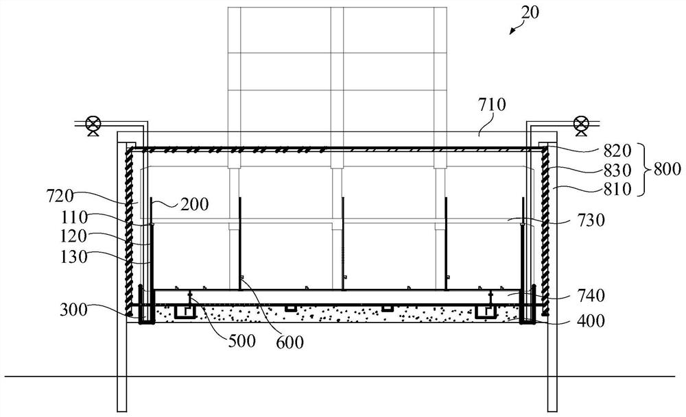
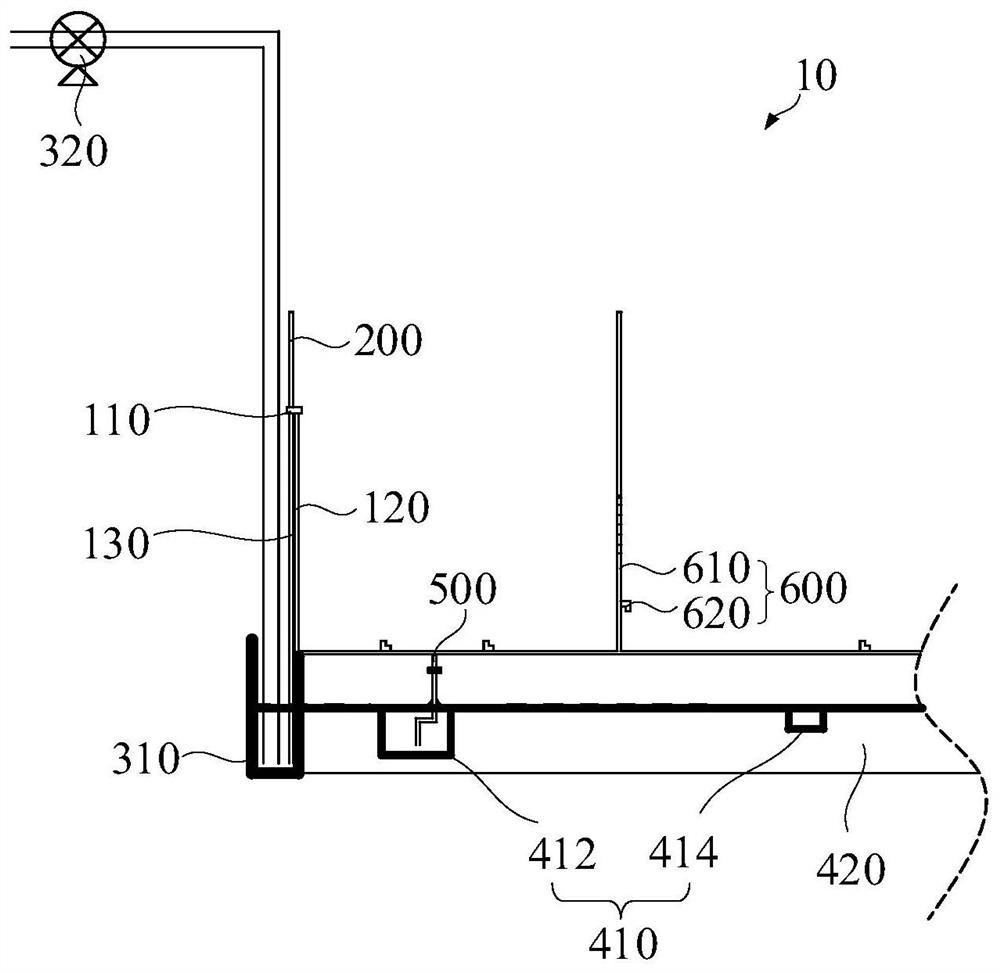
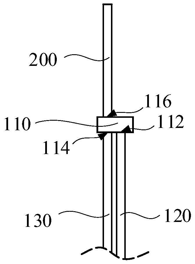
The invention discloses a water-carrying floating-reducing and floating-resisting system and a basement structure. The water-carrying floating-reducing and floating-resisting system comprises a reservoir, a water inlet pipe and a water outlet pipe. The reservoir is provided with a water inlet, a water outlet and an air vent communicating with outside air; the water inlet pipe is used for communicating a water catchment system with the reservoir, and the reservoir is arranged higher than the water catchment system, so that water in the water catchment system overcomes self gravity through the water inlet pipe to flow into the reservoir; and the water outlet pipe is used for communicating a drainage system with the reservoir. The reservoir is arranged above the catchment system, the reservoir is arranged at a position with a certain height so that the height of an underground water head can be maintained below the reservoir, underground water with the height of the underground water head larger than the height of the reservoir is drained through the drainage system, the dead weight of the building can offset buoyancy of the underground water between the reservoir and the catchment system, the requirement for the drainage system is lowered, and drainage cost is reduced. The basement structure can control the height of the underground water head to be below the height of the reservoir all the time.

Description

technical field [0001] The invention relates to the field of basement drainage, in particular to a water-carrying buoyancy-reducing and anti-floating system and a basement structure. Background technique [0002] In the southeastern coastal areas of my country, due to the high groundwater level, buildings usually need anti-floating design. The commonly used anti-floating methods include: anti-lift pile method, drainage and decompression method, and self-weight increase method. Among them, the uplift pile method is the most widely used, but it also has the disadvantages of high cost and long construction period. In order to save investment and improve construction efficiency, many technicians have carried out innovative research on drainage and decompression methods in recent years. In the traditional drainage and decompression method, there is a water-stop curtain around the underground structure, and several sumps are arranged under the bottom plate of the underground stru...

Claims


Application Information

Patent Timeline
IPC IPC(8): E02D31/12E04B1/00
Inventor 黄俊光赵松林李伟科李健斌李磊张恒王维俊王松帆陈香波梁永恒彭浩李健津
Owner 广州市设计院集团有限公司
Learn More