Automatic liquid medicine conveying system

A delivery system and liquid medicine technology, applied in the pipeline system, gas/liquid distribution and storage, mechanical equipment, etc., can solve problems such as fluctuations in liquid medicine delivery, low production efficiency, and changes in flow resistance

Active Publication Date: 2021-11-02
盐城意迪尔流体设备有限公司
View PDF9 Cites 0 Cited by
  • Summary
  • Abstract
  • Description
  • Claims
  • Application Information

AI Technical Summary

Problems solved by technology

At present, when laying pipes in the conveying system, due to the need for some adjustments to the structure of the site itself or the need to change the height to meet the actual pipe laying needs, this will cause changes in the energy level, and the flow rate of some sections of the pipe will increase or decrease, which will Changes in flow resistance cause fluctuations in the process of delivering liquid medicine, which is not conducive to the stability of the delivery system and the extension of its service life
In addition, liquid dispensing tank is an indispensable equipment for the pharmaceutical industry, and its cost is relatively high. At present, some enterprises use liquid medicine to transport to liquid dispensing tank. Put it into the liquid mixing tank under the temperature environment, mix and stir, and then fill it to form the final product, such as oral liquid, etc., so the production efficiency is not high, and it needs to be transported to the liquid mixing tank before filling

Method used


Image

  • Automatic liquid medicine conveying system

Examples


Embodiment Construction

[0019] The specific implementation manners of the present invention will be further described below in conjunction with the drawings and examples. The following examples are only used to illustrate the technical solution of the present invention more clearly, but not to limit the protection scope of the present invention.

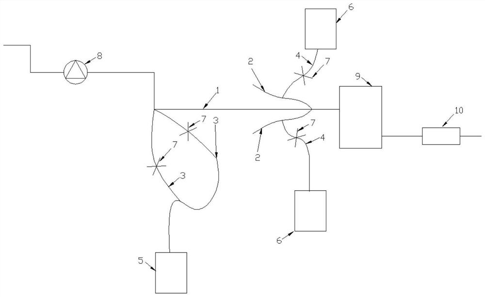
[0020] Such as figure 1 As shown, the present invention is an automatic liquid medicine delivery system, comprising a main pipeline 1 for liquid medicine delivery and a confluence pipeline 2 for mixing different components of medicine liquid; A spare branch 3 that increases fluid velocity due to changes in potential energy. The confluence pipeline 2 communicates with the main pipeline 1, and a confluence pipeline 2 is set corresponding to each component liquid; the confluence pipeline 2 is connected with a branch pipe 4 for keeping the flow rate of each component liquid medicine consistent before mixing. The spare branch pipe 3 is connected with the mixed...


PUM


Abstract

The invention discloses an automatic liquid medicine conveying system. The automatic liquid medicine conveying system comprises a main liquid medicine conveying pipeline and converging pipelines for mixing liquid medicine with different components. The main pipeline is provided with a plurality of standby branch pipes which are used for reducing the flow speed of liquid medicine so as to reduce the increase of the flow speed of fluid caused by the change of conveying potential energy. According to the automatic liquid medicine conveying system, when adjustment or height change is needed to adapt to the actual pipe distribution requirement, the flow speed of the pipeline part of the main pipeline part is increased or decreased, the part where the flow speed is improved is provided with the standby branch pipes, and the opening degree of flow valves is adjusted, so that the flow of divided fluid is adjusted, and the effect of adjusting the flow speed of the fluid in the main pipeline is achieved; and a fluid conveying machine capable of providing higher conveying energy is pre-selected in advance according to a pipe arrangement design drawing for the part with the reduced flow speed. For mixing which only needs normal temperature and normal pressure, the converging pipelines are arranged, so that a subsequent liquid preparation tank is directly omitted, the liquid preparation process is synchronously completed on line in the conveying process, the production efficiency is improved, and the number of equipment of a subsequent system is reduced.

Description

technical field [0001] The invention relates to an automatic medicinal liquid delivery system. Background technique [0002] In the liquid medicine transportation, the pipeline equipment material is generally 316L stainless steel, and the liquid conveying machine needs to supply energy to the liquid medicine to transport the liquid medicine from the low energy level to the high energy level, and the liquid medicine is subject to flow resistance when flowing in the pipeline. Since the flow resistance increases with the increase of the flow velocity, it is required that the mechanical energy added by the fluid delivery machine to the unit weight of the fluid, that is, the liquid medicine, increases with the increase of the flow velocity. At present, when laying pipes in the conveying system, the structure of the site itself needs to be adjusted or the height needs to be changed to meet the actual pipe laying needs. Changes in the flow resistance cause fluctuations in the proc...

Claims


Application Information

Patent Timeline
IPC IPC(8): F17D1/14F17D3/01
CPCF17D1/14F17D3/01
Inventor 白文军
Owner 盐城意迪尔流体设备有限公司
Why Eureka
Try Eureka