
Automatic discharging device

A technology of automatic unloading device and unloading pipe, which is applied in the direction of reactor fuel elements, reactors, greenhouse gas reduction, etc., to achieve the effect of reducing space requirements and reducing intervention

Pending Publication Date: 2021-11-02
SHANGHAI INST OF APPLIED PHYSICS - CHINESE ACAD OF SCI
View PDF0 Cites 0 Cited by
  • Summary
  • Abstract
  • Description
  • Claims
  • Application Information

AI Technical Summary

Problems solved by technology

[0005] The purpose of the present invention is to provide an automatic unloading device to solve the problem of unloading spent fuel in the TMSR molten salt reactor in a narrow space, high temperature, molten salt and irradiation environment

Method used


Image

  • Automatic discharging device
  • Automatic discharging device
  • Automatic discharging device

Examples


Embodiment Construction

[0039] Below in conjunction with the drawings, preferred embodiments of the present invention are given and described in detail.

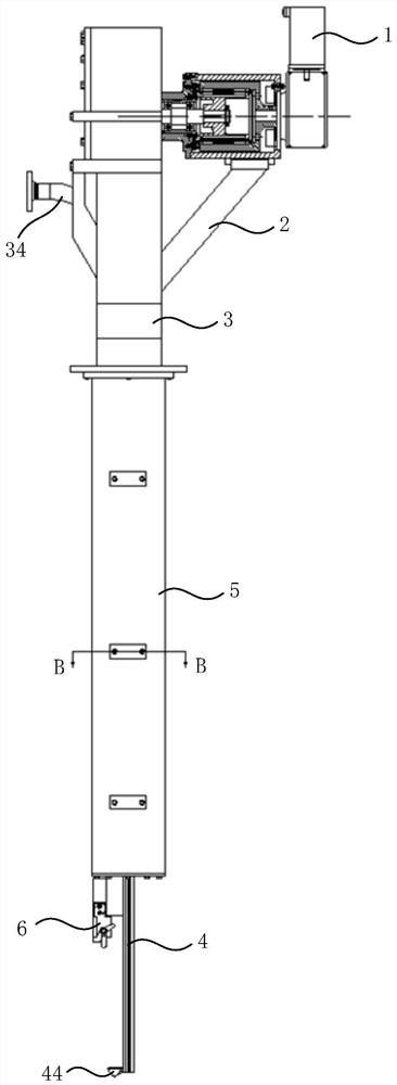
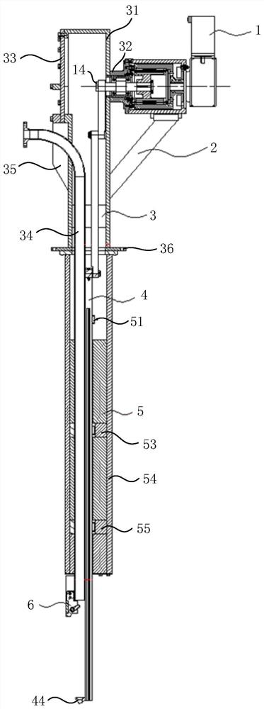
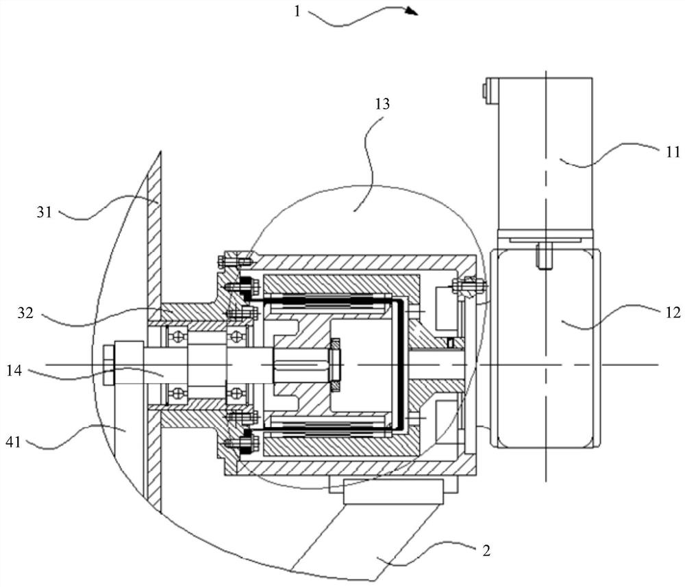
[0040] Such as figure 1 and figure 2 As shown, the present invention provides an automatic unloading device, which can be used in a TMSR molten salt reactor, including a drive mechanism 1, a shielding cylinder assembly 3, an actuator 4, a guiding mechanism 5 and a jacking mechanism 6, wherein the shielding cylinder assembly 3 It includes a shielding cylinder 31 and a discharge pipe 34 welded on the shielding cylinder 31. One end of the discharge pipe 34 protrudes from the wall of the shielding cylinder 31, and the other end extends downward along the inside of the shielding cylinder 31 out of the guide mechanism 5. ; The driving mechanism 1 is fixed on the outside of the wall of the shielding tube 31, and a transmission shaft 14 extends into the inside of the shielding tube 31; the guide mechanism 5 is fixed on the lower end of the shielding tube...


PUM


Abstract

The invention relates to an automatic discharging device which comprises a shielding cylinder assembly, a driving mechanism, a guide mechanism, an executing mechanism and a jacking mechanism, wherein shielding cylinder assembly comprises a shielding cylinder and a discharging pipe; the driving mechanism is fixed on the outer side of the cylinder wall of the shielding cylinder, and a transmission shaft of the driving mechanism penetrates through the cylinder wall of the shielding cylinder and extends into the shielding cylinder; the guide mechanism is connected to the lower end of the shielding cylinder and is communicated with the interior of the shielding cylinder; one end of the executing mechanism is connected with the transmission shaft of the driving mechanism, and the other end of the executing mechanism downwards extends out of the guide mechanism; the jacking mechanism is fixed at the lower end of the discharging pipe; and one end of the discharging pipe penetrates out of the cylinder wall of the shielding cylinder, and the other end of the discharging pipe axially and downwards extends out of the guide mechanism from the interior of the shielding cylinder. According to the automatic discharging device, movement of the executing mechanism is controlled through the driving mechanism, vertical movement of the executing mechanism is guaranteed through the guide mechanism, spent fuel balls are picked up and conveyed through cooperation with the jacking mechanism, intervention of other equipment is reduced, and the space requirement of the equipment is lowered.

Description

technical field [0001] The invention relates to the field of nuclear reactor equipment, in particular to an automatic unloading device for nuclear reactors. Background technique [0002] Spent fuel refers to the nuclear fuel in the nuclear fuel assembly that is unloaded from the reactor and is no longer used in the reactor after the nuclear reaction has occurred through neutron bombardment and the burnup depth has reached the design discharge burnup. [0003] At present, the forms of fuel used in reactors already in service or under development at home and abroad are mainly divided into two types, namely liquid fuel and solid fuel. The main structural form of solid fuel can refer to the fuel assembly of pressurized water reactor and high temperature gas-cooled reactor. spherical fuel elements. Compared with liquid fuel and PWR fuel assemblies, the advantage of using spherical fuel elements is that it can realize non-stop refueling, and the unloading device is one of the imp...

Claims


Application Information

Patent Timeline
IPC IPC(8): G21C19/02G21C19/10
CPCG21C19/02G21C19/10Y02E30/30
Inventor 张丽娜曹云李林玉朱世峰翟利芳胡瑞荣
Owner SHANGHAI INST OF APPLIED PHYSICS - CHINESE ACAD OF SCI
Learn More