
Array substrate and display panel

A technology of array substrate and display area, which is applied to static indicators, digital memory information, instruments, etc., can solve the problems of different scanning signal delays and different number of scanning lines, etc., so as to reduce delay errors and signal differences. , the effect of improving synchronization and coordination

Pending Publication Date: 2021-11-02
WUHAN TIANMA MICRO ELECTRONICS CO LTD
View PDF10 Cites 0 Cited by
  • Summary
  • Abstract
  • Description
  • Claims
  • Application Information

AI Technical Summary

Problems solved by technology

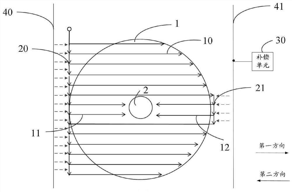
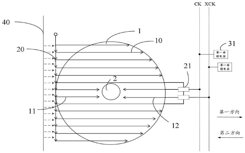
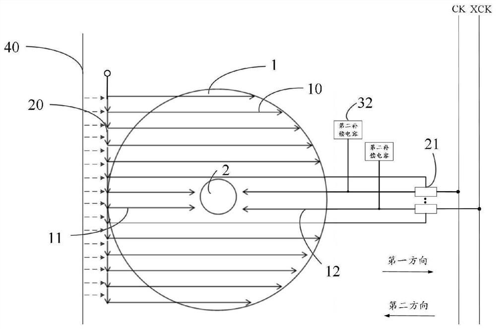
[0005] The embodiment of the present application provides an array substrate and a display panel, which can solve the technical problem that the number of scanning lines arranged on both sides of the opening area is inconsistent, resulting in different delays of the received scanning signals

Method used


Image

  • Array substrate and display panel
  • Array substrate and display panel
  • Array substrate and display panel

Examples


Embodiment Construction

[0028] The characteristics and exemplary embodiments of various aspects of the application will be described in detail below. In order to make the purpose, technical solution and advantages of the application clearer, the application will be further described in detail below in conjunction with the accompanying drawings and specific embodiments. It should be understood that the specific embodiments described here are only intended to explain the present application rather than limit the present application. It will be apparent to one skilled in the art that the present application may be practiced without some of these specific details. The following description of the embodiments is only to provide a better understanding of the present application by showing examples of the present application.

[0029] It should be noted that in this article, relational terms such as first and second are only used to distinguish one entity or operation from another entity or operation, and d...


PUM


Abstract

The invention discloses an array substrate and a display panel. The display panel comprises a display area, an opening area, a plurality of first scanning lines, a plurality of second scanning lines, a plurality of third scanning lines, a plurality of first shifting register units, a plurality of second shifting register units and a compensation unit. The first scanning lines pass through the display area along a first direction; the second scanning lines extend to the opening area in the first direction; the third scanning lines extend to the opening area along a second direction; the output ends of the first shifting register units are connected with the corresponding first scanning lines and second scanning lines respectively, and the output ends of the second shifting register units are connected with the corresponding third scanning lines. The first scanning lines penetrate through the display area to be connected with the second shifting register units, and the compensation unit is connected into a scanning signal loop composed of a second clock signal line, the second shifting register units and the third scanning lines. According to the embodiment of the invention, the capacitance difference of the wires on the two sides of the display area can be compensated, and the delay difference of scanning signals is reduced.

Description

technical field [0001] The present application belongs to the field of display technology, and in particular relates to an array substrate and a display panel. Background technique [0002] At present, with the diversification of designs of electronic products, holes are usually dug in the display area of ​​the display screen of the electronic products to form an opening area, and various electronic components are placed in the opening area. Such as camera or watch hands etc. Wherein, the shapes of the display area and the opening area can also be varied. [0003] However, in the array substrate of electronic products, in order to bypass the hole area in the display area, various traces need to be wound in an arc near the hole area so as to avoid the hole area. However, if the winding wires near the hole area are too dense, black borders will be formed in the non-display area, making the frame of the hole area too large. Therefore, the existing solution is usually to set ...

Claims


Application Information

Patent Timeline
Patent Type & Authority Applications(China)
IPC IPC(8): H01L27/12G09G3/20G11C19/28
CPCH01L27/1214H01L27/124G09G3/20G11C19/28G09G2310/0286
Inventor 张鹏
Owner WUHAN TIANMA MICRO ELECTRONICS CO LTD
Learn More