
Electronic equipment

A technology of electronic equipment and feeder terminal, which is applied in the field of electronic equipment with wireless communication function, can solve the problems of poor antenna radiation performance, achieve the effect of enhanced magnetic field coupling and improved radiation performance

Active Publication Date: 2021-11-02
LENOVO (BEIJING) LTD
View PDF8 Cites 1 Cited by
  • Summary
  • Abstract
  • Description
  • Claims
  • Application Information

AI Technical Summary

Problems solved by technology

The existing antenna circuit with two feed terminals is generally connected to the same radiator, and the antenna radiation performance is poor

Method used


Image

  • Electronic equipment
  • Electronic equipment
  • Electronic equipment

Examples


Embodiment Construction

[0034] The following will clearly and completely describe the embodiments of the present application with reference to the drawings in the embodiments of the present application. Obviously, the described embodiments are only some of the embodiments of the present application, not all of them. Based on the embodiments in this application, all other embodiments obtained by persons of ordinary skill in the art without making creative efforts belong to the scope of protection of this application.

[0035] In order to make the above objects, features and advantages of the present application more obvious and comprehensible, the present application will be further described in detail below in conjunction with the accompanying drawings and specific implementation methods.

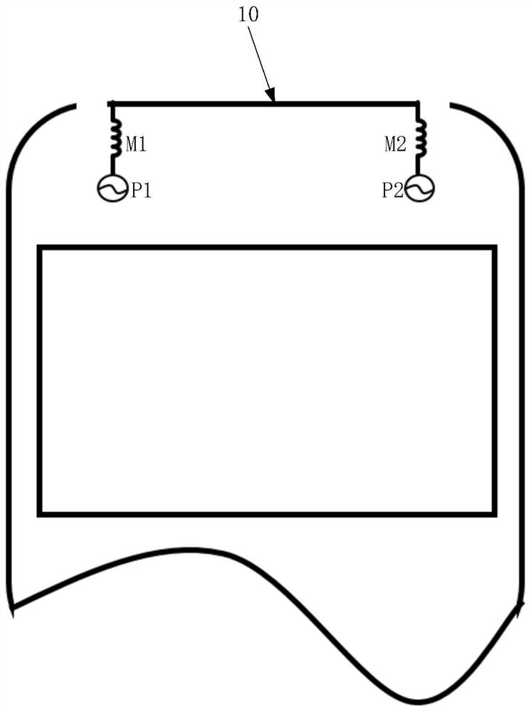
[0036] Such as figure 1 as shown, figure 1 It is a structural schematic diagram of a conventional electronic device, the electronic device shown is a wireless communication electronic device with a metal casing, ...


PUM


Abstract

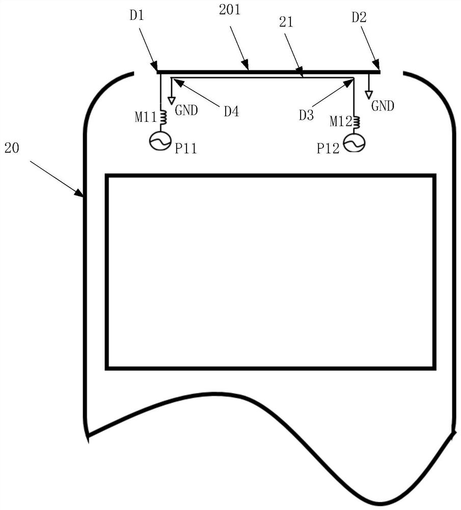
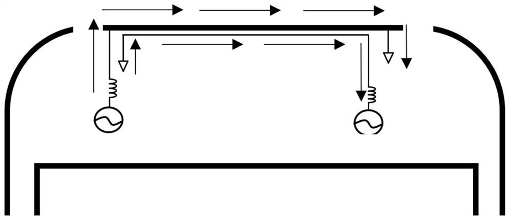
The invention discloses electronic equipment, the electronic equipment is provided with a first radiation branch and a second radiation branch, the first radiation branch is connected with a first feed end of an antenna circuit, and the second radiation branch is connected with a second feed end of the antenna circuit. The first radiation branch at least partially surrounds the second radiation branch, and the current directions in the first radiation branch and the second radiation branch are the same, so that magnetic field coupling in two antenna branches can be enhanced, and the radiation performance of the antenna is improved.

Description

technical field [0001] The present application relates to the technical field of wireless communication, and more specifically, relates to an electronic device with a wireless communication function. Background technique [0002] With the continuous advancement of science and technology, more and more electronic devices with wireless communication functions are widely used in people's daily life and work, which brings great convenience to people's daily life and work, and has become the Indispensable and important tool. [0003] The main component of electronic equipment to realize the wireless communication function is the antenna, and the antenna needs to send and receive signals through the radiator. The existing antenna circuit with two feeding terminals is generally connected to the same radiator, and the radiation performance of the antenna is poor. Contents of the invention [0004] In view of this, the application provides an electronic device, the scheme is as f...

Claims


Application Information

Patent Timeline
Patent Type & Authority Applications(China)
IPC IPC(8): H01Q1/36H01Q1/50H01Q1/22
CPCH01Q1/36H01Q1/50H01Q1/22
Inventor 林郁喆
Owner LENOVO (BEIJING) LTD
Learn More