Quadruple Helix Antenna Based on Multiple Loading Structure

A four-arm helical and multiple loading technology, which is applied in the directions of antenna, antenna coupling, antenna components, etc., can solve the problem that the gain of low elevation angle cannot meet the communication requirements of ground equipment, the large installation platform of the four-arm helical antenna has great influence, and the gain reaches It meets the needs of wide-beam radiation pattern, weakens the influence, and increases the gain of low elevation angle without meeting the communication requirements of ground equipment and other issues.

Active Publication Date: 2022-07-01
XIDIAN UNIV
View PDF12 Cites 0 Cited by
  • Summary
  • Abstract
  • Description
  • Claims
  • Application Information

AI Technical Summary

Problems solved by technology

[0007] The purpose of the present invention is to address the deficiencies in the prior art above, and propose a quadrifilar helical antenna based on multiple loading structures, which solves the problem that the gain at low elevation angles cannot be reached when the existing quadrifilar helical antenna is used as a ground end antenna. The problem of communication requirements with ground equipment, and the problem that the wide-beam circularly polarized radiation pattern of the existing quadrifilar helical antenna is greatly affected by the large installation platform
The vertical part of the parasitic ring and the "hat-shaped" metal structure can be regarded as a radiation director, and the coupling current generated on its surface guides part of the radiation energy to the wide-angle direction, so that the radiation in the original wide-angle direction of the antenna The energy distribution is enhanced, and the gain at low elevation angles near the horizontal plane is increased, which solves the problem that when the existing quadrifilar helical antenna is used as a ground end antenna, the gain at low elevation angles cannot meet the communication requirements with ground equipment

Method used


Image

  • Quadruple Helix Antenna Based on Multiple Loading Structure
  • Quadruple Helix Antenna Based on Multiple Loading Structure
  • Quadruple Helix Antenna Based on Multiple Loading Structure

Examples


Embodiment Construction

[0020] The present invention will be further described in detail below with reference to the accompanying drawings and embodiments.

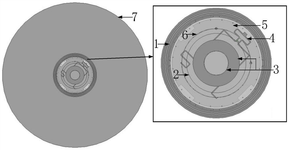
[0021] refer to figure 1 , and further describe the overall structure of the antenna of the present invention.

[0022] The antenna of the present invention includes a laminated cavity 1 , a parasitic ring 2 , a “hat-shaped” parasitic structure 3 , a double-layer feeding network 4 , a reflection floor 5 , and a helical antenna assembly 6 . The four-armed helical antenna is installed in the center of the platform 7 . The laminated cavity 1 is the outermost layer of the four-armed helical antenna. Inside the laminated cavity 1, a helical antenna assembly 6, a parasitic ring 2 and a "hat-shaped" parasitic structure 3 are sequentially arranged; the laminated cavity 1 , the helical antenna assembly 6, the parasitic ring 2 and the "hat-shaped" parasitic structure 3 have the same centers of circles; cylindrical steps are etched inside the laminated c...


PUM


Abstract

The present invention discloses a four-armed helical antenna based on a multiple loading structure, comprising a laminated cavity 1, a parasitic ring 2, a "hat-shaped" parasitic structure 3, a double-layer feeding network 4, a reflection floor 5, and a helical antenna assembly 6 . The four-armed helical antenna is installed in the center of the platform 7 . The laminated cavity 1 is the outermost layer of the four-armed helical antenna. Inside the laminated cavity 1, a helical antenna assembly 6, a parasitic ring 2 and a "hat-shaped" parasitic structure 3 are arranged in sequence. Due to the coupling current generated on the surface of the parasitic ring 2 and the "hat-shaped" metal structure 3 of the present invention, part of the radiated energy is directed to the wide-angle direction, so that the low-elevation-angle gain near the horizontal plane of the antenna is increased. The laminated cavity 1 restrains the helical antenna assembly from exciting the coupling current on the surface of the platform 7, thus weakening the influence of the platform 7 on the wide beam radiation pattern of the quadrifilar helical antenna. Therefore, the antenna of the present invention can be used as a ground-end antenna in a satellite-to-ground communication system.

Description

technical field [0001] The invention belongs to the technical field of antennas, and further relates to a four-armed helical antenna based on a multiple loading structure among the helical antennas. The present invention can be used as a ground-end antenna in a satellite-to-ground communication system. Background technique [0002] The antenna is an important component in the satellite-to-ground communication system, which directly affects the performance of the entire system. Therefore, it is very important to study the antenna applied to the satellite-to-ground communication system. The ground-side antenna used for satellite-to-ground communication needs to realize communication with ground-side equipment and satellite-side equipment. When the ground-side antenna communicates with the ground-side equipment, it mainly relies on the low-elevation signal with vertical linear polarization close to the ground. Although the zenith signal is easy to receive and transmit, it has...

Claims


Application Information

Patent Timeline
Patent Type & Authority Patents(China)
IPC IPC(8): H01Q1/36H01Q1/00H01Q1/24H01Q1/38H01Q1/52
CPCH01Q1/36H01Q1/002H01Q1/241H01Q1/52H01Q1/38
Inventor 张凡冯云霞张福顺
Owner XIDIAN UNIV
Why Eureka
Try Eureka