Automatic control cabinet

A technology for control cabinets and cabinets, applied in the field of control cabinets, can solve the problems of deep operating space, inconvenience for maintenance personnel, laborious search or maintenance of faulty devices, etc., and achieve the effect of sufficient light, convenient maintenance, and convenient two-handed operation

Pending Publication Date: 2021-11-02
JILIN TOBACCO IND
View PDF0 Cites 0 Cited by
  • Summary
  • Abstract
  • Description
  • Claims
  • Application Information

AI Technical Summary

Problems solved by technology

[0003] Most of the existing automation control cabinets have a cabinet structure, and all components are installed in the cabinet, which brings great inconvenience to the maintenance personnel
For example, because the depth of the cabinet is usually deep, the operating space is deep and narrow, and maintenance personnel need to find or repair faulty devices or faulty lines in the cabinet in an extremel

Method used


Image

  • Automatic control cabinet
  • Automatic control cabinet
  • Automatic control cabinet

Examples


Example Embodiment

[0025] Next, the technical solutions in the embodiments of the present invention will be described in connection with the drawings of the embodiments of the present invention, and it is understood that the described embodiments are merely the embodiments of the present invention, not all of the embodiments. Based on the embodiments of the present invention, all other embodiments obtained by those of ordinary skill in the art are in the range of the present invention without making creative labor premise.

[0026] In order to better understand the present invention, the present invention will be described in detail below with reference to the accompanying drawings and specific embodiments.
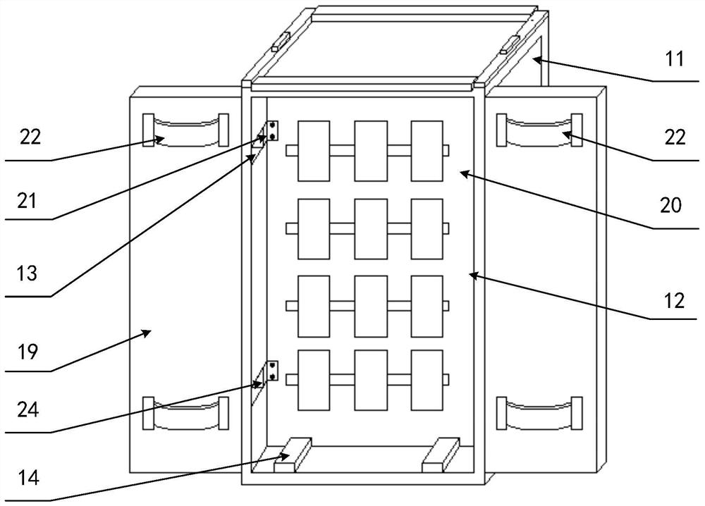
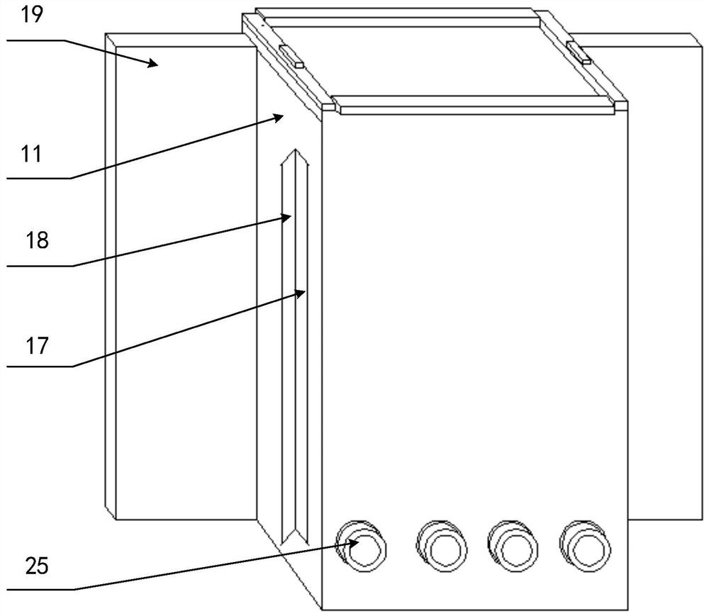
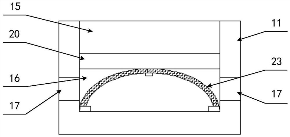
[0027] Please refer to Figure 1 to 4 , figure 1 A front view of the automated control cabinet provided by the embodiment of the present invention; figure 2 for figure 1 Rear schematic; image 3 for figure 1 Cross sectional diagram of the middle cabinet; Figure 4 for figure 1 Structure diagram of...


PUM


Abstract

The invention discloses an automatic control cabinet, which comprises a cabinet body, a cabinet door and a mounting plate slidably mounted in the cabinet body. An inward-pushing elastic member and an outward-pushing elastic member are respectively arranged at two sides of the mounting plate, the inward-pushing elastic member is fixedly arranged on the cabinet door, and the outward-pushing elastic member is located in an inner side cavity formed by the mounting plate and the cabinet body. When maintenance is completed, the cabinet door is closed, and the inward-pushing elastic member pushes the mounting plate to overcome the elastic force of the outward-pushing elastic member and slide towards the interior of the cabinet body. During maintenance, the cabinet door is opened, the extrusion force applied to the mounting plate by the inward-pushing elastic member disappears, the outward-pushing elastic member recovers the elastic deformation, the outward-pushing elastic member reversely pushes the mounting plate to slide towards the opening by means of the elastic force of the outward-pushing elastic member, the mounting plate is close to the opening, light is sufficient, and a maintainer can maintain the cabinet without leaning into the cabinet body or holding a lighting tool by hand. And double-hand operation is convenient, and maintenance is convenient.

Description

technical field [0001] The invention relates to the field of control cabinets, in particular to an automatic control cabinet. Background technique [0002] With the improvement of the automation level, more and more large-scale equipment or combined equipment are equipped with special automation control cabinets. The automation control cabinets usually store the power supply, central processing unit, memory, functional modules and communication modules together for Complete specific control functions, involving various fields, the application is more common. [0003] Most of the existing automation control cabinets have a cabinet structure, and various components are installed in the cabinet, which brings great inconvenience to the maintenance personnel. For example, because the depth of the cabinet is usually deep and the operating space is deep and narrow, maintenance personnel need to find or repair faulty devices or faulty lines in the cabinet in an extremely uncomforta...

Claims


Application Information

Patent Timeline
IPC IPC(8): H02B1/38H02B1/32H02B1/54H02B1/36H02B1/56H02B1/28H02B1/20
CPCH02B1/38H02B1/32H02B1/54H02B1/36H02B1/565H02B1/28H02B1/20
Inventor 李志强
Owner JILIN TOBACCO IND
Why Eureka
Try Eureka