Intelligent instrument and meter fixing and clamping device facilitating heat dissipation
A technology for fixed clamping of instruments and meters, which is applied in the field of fixed clamping devices for intelligent instruments and meters, which can solve problems such as adhesion or blockage, slowness, overheating damage of instruments, etc., and achieve the effects of improving heat dissipation, preventing damage, and simple operation
- Summary
- Abstract
- Description
- Claims
- Application Information
AI Technical Summary
Problems solved by technology
Method used
Image
Examples
Embodiment 1
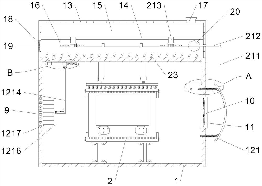
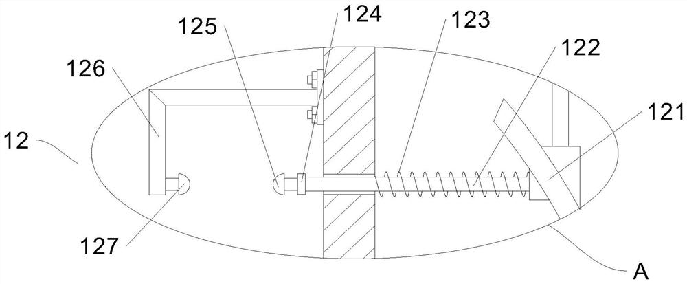
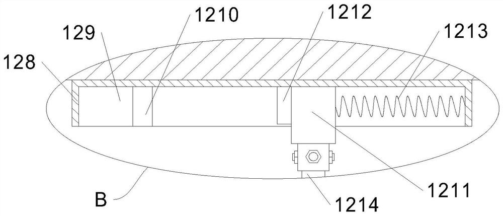
[0033] In this embodiment, as shown in Figures 1-7, a fixed and clamping device for intelligent instruments and meters that is convenient for heat dissipation includes a housing 1, a side door is provided at the front end of the housing 1, and a rear wall of the housing 1 is provided for wires. Through the through hole, and one end of the housing 1 is fixed through the ventilation plate 9 with a plurality of ventilation openings, the other end of the housing 1 is fixed through the through shell 10, and the fan 11 is installed in the through shell 10 The housing 1 is provided with clamping parts for clamping the instrument. The clamping parts include clamping plates 2 symmetrically arranged vertically. Sliding rods 6 are symmetrically fixed at the top, sleeves 7 are slidably connected to the tops of the two sliding rods 6, the tops of the two sleeves 7 are fixed to the top wall of the housing 1, and the sleeve 7 and the sliding rod 6 pass through The locking screws 8 are corres...
Embodiment 2
[0037] On the basis of Embodiment 1, both sides of the inner ends of the two splints 2 are fixed with limiting plates 3 for preventing instrument deviation. The inner ends of the two splints 2 are fixed with a plurality of cooling plates 22 at intervals, which is conducive to the timely circulation and export of the heat dissipated by the instrument.
Embodiment 3
[0039] On the basis of Embodiment 2, the top of the housing 1 is fixed with a box body 13 with an unclosed bottom end, and the inner wall of the box body 13 is divided into a cavity one 15 and a cavity two 16 through a partition 14, and the top of the cavity one 15 The wall is connected to the water injection pipe 17 with a sealing cover, the side wall of the cavity 2 16 is fixed with a through shell 2 18, and the fan 2 19 is installed in the through shell 2 18, and the rear wall of the cavity 2 16 is provided with a heat dissipation port 20. The cavity two 16 is provided with a water discharge mechanism 21 . The water discharge mechanism 21 includes two discharge pipes 213 that symmetrically pass through the partition plate 14 and communicate with the cavity one 15. The bottom ends of the two discharge pipes 213 are fixed with a round block one 214, and the bottom ends of the two round block one 214 are all rotated. The two round blocks 215 are connected, and the two round bl...
PUM
 Abstract
Description
Claims
Application Information
 - R&D
- Intellectual Property
- Life Sciences
- Materials
- Tech Scout
- Unparalleled Data Quality
- Higher Quality Content
- 60% Fewer Hallucinations
Browse by: Latest US Patents, China's latest patents, Technical Efficacy Thesaurus, Application Domain, Technology Topic, Popular Technical Reports.
© 2025 PatSnap. All rights reserved.Legal|Privacy policy|Modern Slavery Act Transparency Statement|Sitemap|About US| Contact US: help@patsnap.com


