Mixing equipment for flame-retardant thermoplastic polyurethane elastomer

A thermoplastic polyurethane and mixing equipment technology, which is applied in the field of flame retardant material processing, can solve the problems of insufficient material mixing effect and too simple mixing and stirring structure, and achieve the effects of easy processing, stable structure, and guaranteed stability

Inactive Publication Date: 2021-11-05
李宁
View PDF0 Cites 0 Cited by
  • Summary
  • Abstract
  • Description
  • Claims
  • Application Information

AI Technical Summary

Problems solved by technology

[0010] The purpose of the present invention is to provide a kind of mixing equipment for flame-retardant thermoplastic polyurethane elastomers, to solve the problem that the mixing and stirring structure is too simple in the above-mentioned background technology, resulting in insufficient mixing effect between materials

Method used


Image

  • Mixing equipment for flame-retardant thermoplastic polyurethane elastomer
  • Mixing equipment for flame-retardant thermoplastic polyurethane elastomer
  • Mixing equipment for flame-retardant thermoplastic polyurethane elastomer

Examples


Embodiment 1

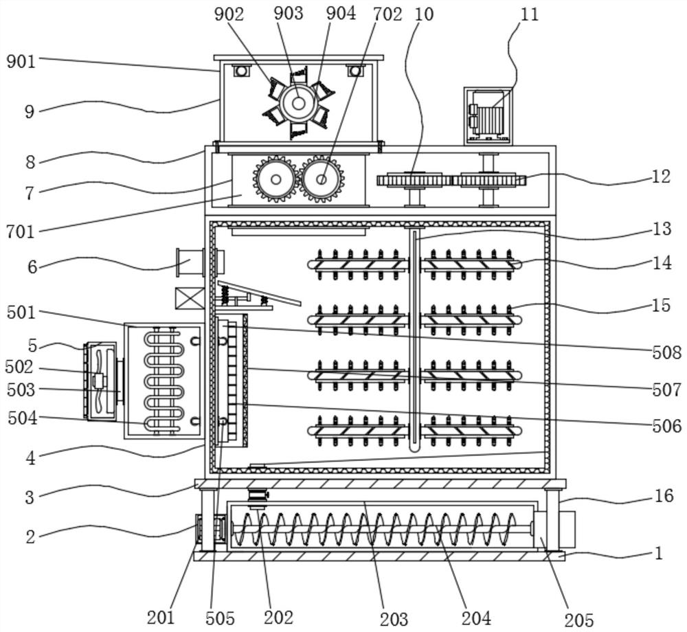
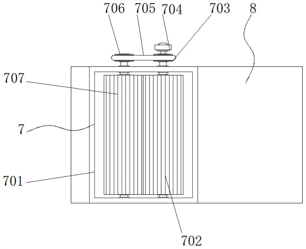
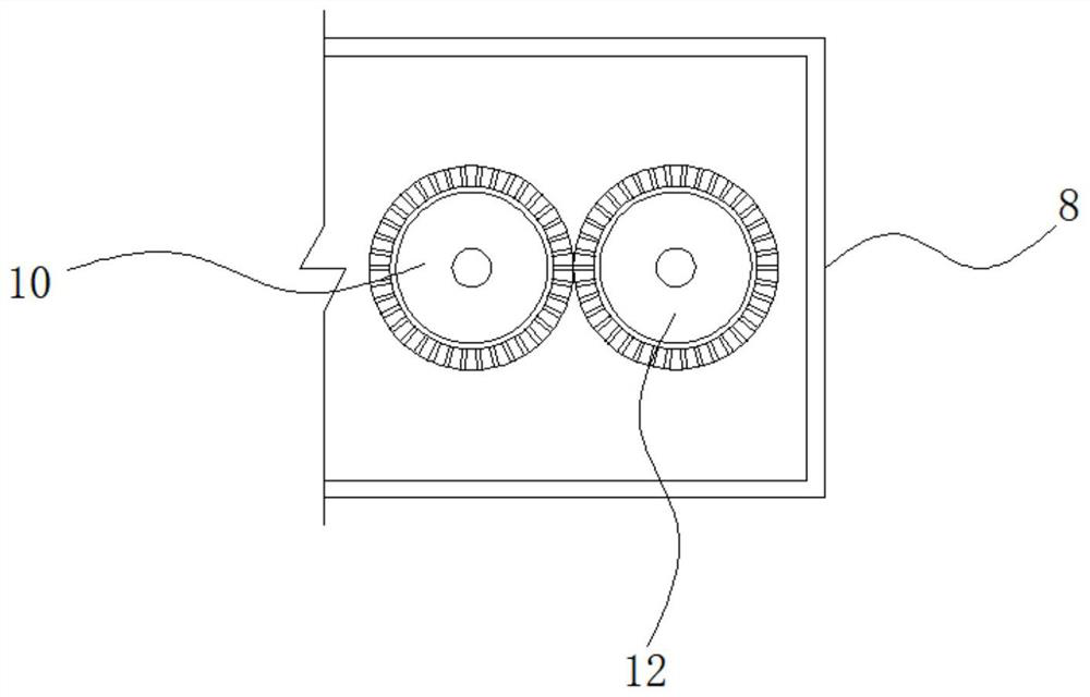
[0038] Example 1: See Figure 1-7 , a mixing device for flame-retardant thermoplastic polyurethane elastomers, comprising a device main body 4, the bottom end of the device main body 4 is fixedly connected with a top plate 3, the two sides of the bottom end of the top plate 3 are fixedly connected with support rods 16, and the bottom ends of the support rods 16 A bottom plate 1 is fixedly connected, a uniform discharge mechanism 2 is arranged between the top plate 3 and the bottom plate 1, a placement seat 8 is fixedly connected to the top of the equipment main body 4, and a feeding mechanism 9 is provided on the top side of the placement seat 8, and the inside of the placement seat 8 A crushing mechanism 7 is provided on one side of the device body 4, a heating mechanism 5 is provided on one side of the device body 4, a water inlet 6 is fixedly connected to the top of one side of the device body 4, and a mixing and stirring mechanism is provided inside the device body 4;

[0...

Embodiment 2

[0042] Embodiment 2: The uniform discharge mechanism 2 is composed of a first drive motor 201, a material guide pipe 202, a fixed seat 203, a screw conveying rod 204, and a discharge port 205. The fixed seat 203 is fixedly connected to the top of the bottom plate 1, and the fixed seat 203 The inner top runs through a feed pipe 202, and the top of the feed pipe 202 runs through the bottom end of the equipment main body 4, and the inside of the fixed seat 203 is connected with a screw conveying rod 204 horizontally, and one side of the screw conveying rod 204 passes through the shaft. The connector is fixedly connected to the output end of the first drive motor 201, the model of the first drive motor 201 can be Y90S-2, and the other side of the fixed seat 203 is fixedly connected with a discharge port 205;

[0043] Specifically, as figure 1 As shown, after the material processing is completed, the valve at the material guide pipe 202 is opened, and the first driving motor 201 is...

Embodiment 3

[0044] Embodiment 3: The heating mechanism 5 is composed of a connecting seat 501, an air intake fan 502, a ventilation pipe 503, a heating pipe 504, a duct 505, an air guide pipe 506, an isolation cover 507 and a distribution pipe 508, and the connecting seat 501 is fixedly connected to the bottom plate 1 One side of the connection seat 501 is fixedly connected with a heating pipe 504, the model of the heating pipe 504 can be HVL031-300W, the other side of the connection seat 501 is fixedly connected with a ventilation pipe 503, and one side of the ventilation pipe 503 is fixedly connected to There is an inlet fan 502, the type of the inlet fan 502 can be SF, one side of the connection seat 501 runs through a through pipe 505, two sets of through pipes 505 are provided, and the through pipes 505 are symmetrically distributed about the horizontal center line of the connection seat 501, The other side of the through pipe 505 runs through the interior of the device main body 4 an...


PUM


Abstract

The invention discloses mixing equipment for a flame-retardant thermoplastic polyurethane elastomer. The mixing equipment comprises an equipment main body, the bottom end of the equipment main body is fixedly connected with a top plate, the two sides of the bottom end of the top plate are fixedly connected with supporting rods, the bottom ends of the supporting rods are fixedly connected with a bottom plate, and a uniform discharging mechanism is arranged between the top plate and the bottom plate. A material guiding mechanism is arranged below a water inlet and comprises a third driving motor arranged on the outer wall of the equipment main body, the third driving motor is transversely arranged, a rotating shaft is arranged at the output end of the third driving motor, and the third driving motor, a cam, a spring and a discharging plate are connected in a matched mode. Materials crushed by a crushing mechanism and materials entering from the water inlet can fall on the surface of the discharging plate and fall near a mixing and crushing mechanism through the discharging plate, the material guiding effect is achieved, and the materials can be prevented from being concentrated at the corner of the equipment main body.

Description

technical field [0001] The invention relates to the technical field of flame-retardant material processing, in particular to a mixing device for flame-retardant thermoplastic polyurethane elastomers. Background technique [0002] At present, thermoplastic polyurethane elastomers are widely used in various fields due to their material characteristics, such as shoe materials, plates, cables, films, etc., thermoplastic polyurethane elastomers need to be mixed with other materials evenly during processing to ensure that the materials It has a better flame retardant effect, but there are still some problems in the existing processing equipment of thermoplastic polyurethane elastomers. The mixing and stirring structure is too simple, resulting in insufficient mixing effect between materials. [0003] In the process of realizing the present invention, the inventors have found that at least the following problems in the prior art have not been resolved: [0004] (1) The traditional...

Claims


Application Information

Patent Timeline
Patent Type & Authority Applications(China)
IPC IPC(8): B29B7/16B29B7/22B29B7/24B29B7/26B29B7/82B29B13/10B29K75/00
CPCB29B7/16B29B7/22B29B7/24B29B7/26B29B7/826B29B13/10B29K2075/00
Inventor 李宁
Owner 李宁
Why Eureka
Try Eureka