A hot air conveying device for non-woven fabric production equipment

A technology of production equipment and conveying device, applied in the field of hot air conveying device, can solve the problems of poor cleaning effect of impurities, low degree of automation, poor filtering effect, etc., and achieve the effect of improving the filtering effect and service life, and improving the degree of cleanliness.

Active Publication Date: 2021-12-24
南通莎维纺织品有限公司
View PDF0 Cites 0 Cited by
  • Summary
  • Abstract
  • Description
  • Claims
  • Application Information

AI Technical Summary

Problems solved by technology

[0003] However, the existing hot air conveying device has a poor cleaning effect on impurities in the air. After long-term use, the filter screen will stick to a large amount of impurities, which will lead to poor filtering effect, and it is inconvenient to collect scattered dust in a centralized manner, and the degree of automation is low.

Method used


Image

  • A hot air conveying device for non-woven fabric production equipment
  • A hot air conveying device for non-woven fabric production equipment
  • A hot air conveying device for non-woven fabric production equipment

Examples


Embodiment 1

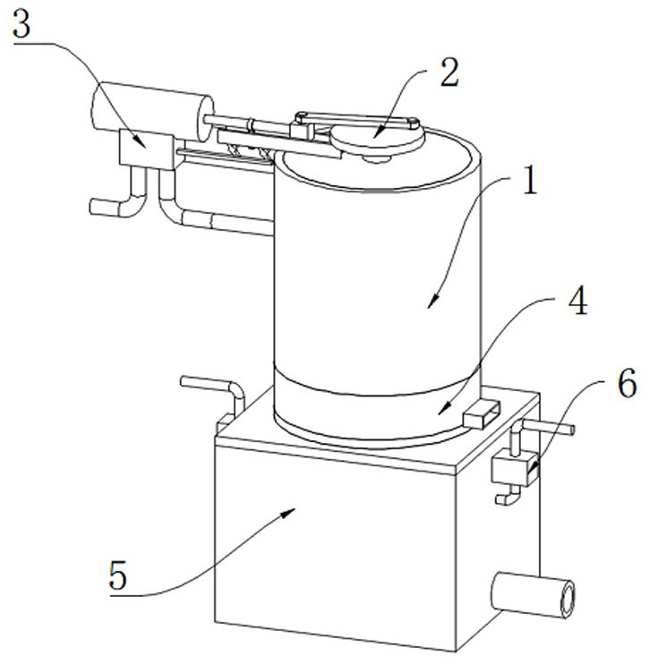
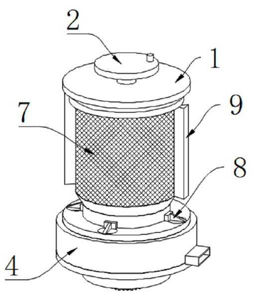
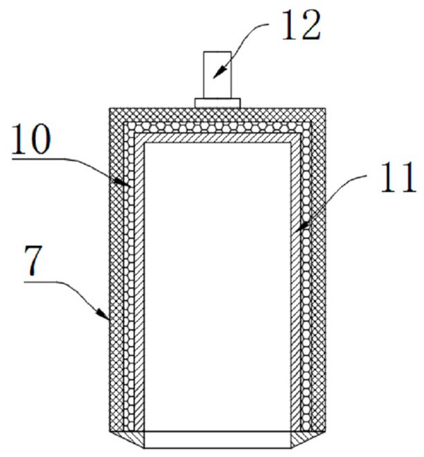
[0032] see figure 2 As shown, a hot air conveying device for non-woven fabric production equipment includes a purification box 1, the top middle of the purification box 1 is movably connected with a rotating shaft 12, and the rotating shaft 12 extends to the inner cavity of the purification box 1 and its bottom is fixed. Connect with filter screen 7, the inwall of filter screen 7 is provided with nano-silver ion layer 10, the inwall of nano-silver ion layer 10 is provided with activated carbon layer 11, and the inwall of purification box body 1 is all fixedly connected with the left and right sides of filter screen 7 The brush plate 9, the top of the rotating shaft 12 is fixedly connected with the turntable 2, and the left side wall of the purification box 1 is fixedly equipped with a steam drive mechanism 3, and its design purpose is: when the push rod 123 moves around periodically, it will push the sliding The block 24 slides left and right in the inner cavity of the chute ...

Embodiment 2

[0034] see Figure 5 As shown, it is basically the same as Embodiment 1. Furthermore, the steam driving mechanism 3 includes a mounting plate 18, the right side wall of the mounting plate 18 is fixedly connected with the left side wall of the purification box 1, and the front of the mounting plate 18 is fixedly installed. Piston cylinder 19 is arranged, and the inner cavity of piston cylinder 19 is slidably connected with piston plate one 35, and the right side wall of piston plate one 35 is fixedly connected with push rod one 23, and the right side wall of push rod one 23 is fixedly connected with slide block 24, The top of the slider 24 is movably connected with a movable plate 25, and the end of the movable plate 25 away from the slider 24 is movably connected with the eccentric position of the turntable 2. The top of the purification box 1 is fixedly connected with a chute 26, and the slider 24 is in the chute 26. The inner chamber of the piston barrel is slidingly connect...

Embodiment 3

[0040] see Figure 8 As shown, it is basically the same as the second embodiment, furthermore, the liquid filling mechanism 6 includes a liquid storage housing 41, the inner cavity of the liquid storage housing 41 is provided with an air bag 42, and the inner cavity of the air bag 42 is provided with a spring 43 transversely, The end of the push rod three 39 away from the gear frame 38 extends to the inner cavity of the liquid storage housing 41 and its end is fixedly connected with the second piston plate 44, the second piston plate 44 is slidingly connected with the inner wall of the liquid storage housing 41, and the top of the air bag 42 and the bottom are provided with a one-way valve connected from top to bottom, the upper one-way valve is externally connected to the disinfectant tank, and the lower one-way valve extends away from the end of the liquid adding mechanism 6 to the inner cavity of the disinfection box 5, and its The end is fixedly connected with a water spra...


PUM


Abstract

The invention discloses a hot air conveying device for non-woven fabric production equipment, which comprises a purification box body, a rotating shaft is movably connected to the middle position of the top of the purification box body, and the rotation shaft extends to the inner cavity of the purification box body and the bottom thereof is fixed. A filter screen is connected, the inner wall of the filter screen is provided with a nano-silver ion layer, the inner wall of the nano-silver ion layer is provided with an activated carbon layer, and the inner wall of the purification box is fixedly connected to the left and right sides of the filter screen. A brush plate, the top of the rotating shaft is fixedly connected with a turntable, and the left side wall of the purification box is fixedly installed with a steam driving mechanism. When the filter screen rotates, it will drive the drum to rotate continuously relative to the inner wall of the dust collection shell. The hole falls into the inner cavity of the dust collecting shell, which is convenient for uniform collection of dust, and the dust in the inner cavity of the dust collecting shell is conveniently cleaned in time by setting the dust outlet.

Description

technical field [0001] The invention relates to the technical field of non-woven fabric processing, in particular to a hot air conveying device of non-woven fabric production equipment. Background technique [0002] Non-woven fabrics have the characteristics of moisture-proof, breathable, flexible, light weight, non-combustible, easy to decompose, non-toxic and non-irritating, rich in color, low in price, and recyclable. For example, polypropylene (pp material) pellets are mostly used as The raw material is produced by continuous one-step process of high-temperature melting, spinning, laying, and hot-pressing coiling, and the non-woven fabric is equipped with a hot air conveying device in the production process, and the hot air is used to ensure the stability of the ambient temperature during the melt-blown spinning stage , to ensure the quality of spinning. [0003] However, the existing hot air conveying device has poor cleaning effect on impurities in the air. After long...

Claims


Application Information

Patent Timeline
Patent Type & Authority Patents(China)
IPC IPC(8): D04H1/56D01D5/084D01D5/098B01D46/00B01D46/24B01D46/26A61L2/18A61L2/26A61L9/16A61L9/00A61L101/04A61L101/02
CPCD04H1/56D01D5/084D01D5/0985B01D46/26B01D46/2411B01D46/0028B01D46/0036A61L2/18A61L2/26A61L9/16A61L9/00A61L2202/15A61L2202/26A61L2209/22A61L2101/02A61L2209/21
Inventor 陈利冬
Owner 南通莎维纺织品有限公司
Why Eureka
Try Eureka