Deceleration strip
A technology of deceleration belts and deceleration units, which is applied to roads, road signs, traffic signals, etc., and can solve the problem that the deceleration belt cannot restrict the passage of cars
- Summary
- Abstract
- Description
- Claims
- Application Information
AI Technical Summary
Problems solved by technology
Method used
Image

Examples
Embodiment 1
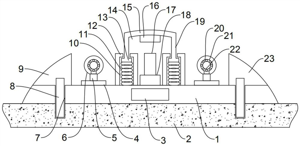
[0035] For ease of understanding, see Figure 1 to Figure 4 , an embodiment of a deceleration belt provided by the application, including a base 1, a controller 3 and a plurality of deceleration units, the deceleration unit includes an uphill section 9, an intermediate section, a downhill section 23, a switch mechanism and a roller mechanism, and a single The length of the deceleration unit is less than the width between the two side-by-side tires of the car.
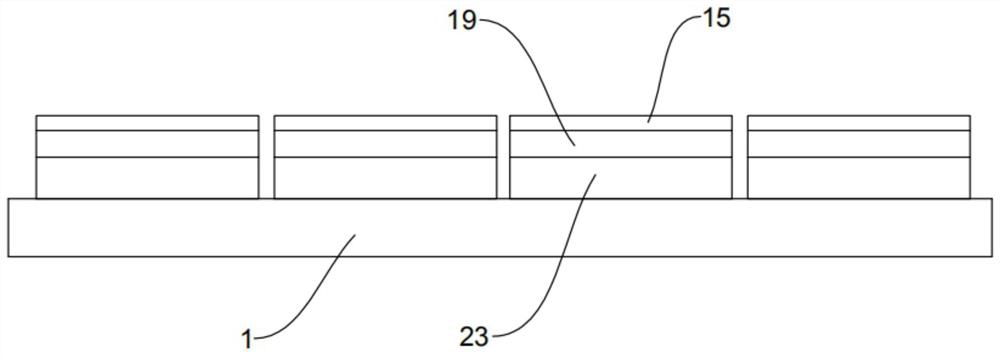
[0036] The base 1 is a rectangular parallelepiped rubber plate, the length of the base 1 is as long as the width of the road 2, the base 1 is provided with a through hole 7, and the expansion screw 8 passes through the through hole 7 to fix the base 1 on the road 2. The deceleration units are arranged on the base 1 in sequence, and gaps are reserved between the deceleration units.
[0037] The uphill section 9 is arranged on one long edge of the upper surface of the base 1, the downhill section 23 is arranged on the ot...
Embodiment 2
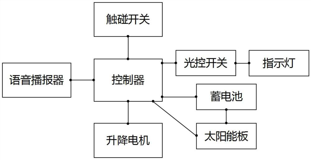
[0044] For ease of understanding, see Figure 1 to Figure 4 , as a further improvement of the speed bump in Embodiment 1, this embodiment also includes a solar panel and a battery, the battery is arranged on the base 1, the solar panel is arranged on the ground through a bracket, and the battery is connected to the solar panel and the controller respectively 3 are electrically connected, and the solar panel can also be directly electrically connected to the controller 3 to directly supply power to the controller 3 .
[0045] The outer surfaces of the uphill section 9 and the downhill section 23 are provided with indicator lights, which are electrically connected to the controller 3 .
[0046] Adjacent deceleration units are provided with indicator lights of different light colors.
[0047] The deceleration unit is provided with a light control switch, and the indicator light is electrically connected with the controller 3 through the light control switch.
[0048] The base 1...
Embodiment 3
[0051] For ease of understanding, see Figure 1 to Figure 4 , In this embodiment, as a further improvement on the deceleration belt in Embodiment 1, the outer layer of the roller 6 is made of rubber.
[0052] Anti-slip stripes are provided on the uphill section 9 and the downhill section 23 .
[0053] A spring 11 is vertically arranged in the chute 10 , and the spring 11 is arranged below the limiting block 13 , and the spring 11 pushes the limiting block 13 against the lower end of the blocking block 12 .
[0054] The top of the touch switch 17 is provided with a rubber pad.
[0055] It should be noted that the rubber has the function of shock absorption and buffering, and the material of the outer layer of the drum 6 is made of rubber, which can prevent the drum 6 from being damaged when collided with the vehicle and squeezed. Anti-slip stripes are set on the uphill section 9 and the downhill section 23, so that the vehicle is not easy to skid when passing the speed bump. ...
PUM
 Abstract
Description
Claims
Application Information
 - R&D
- Intellectual Property
- Life Sciences
- Materials
- Tech Scout
- Unparalleled Data Quality
- Higher Quality Content
- 60% Fewer Hallucinations
Browse by: Latest US Patents, China's latest patents, Technical Efficacy Thesaurus, Application Domain, Technology Topic, Popular Technical Reports.
© 2025 PatSnap. All rights reserved.Legal|Privacy policy|Modern Slavery Act Transparency Statement|Sitemap|About US| Contact US: help@patsnap.com