Pile foundation self-balancing test device with balance point compensation function and test method
The technology of a test device and test method, which is applied in the test of foundation structure, foundation structure engineering, construction, etc., can solve the problem of inaccurate determination of the balance point of pile foundation, and achieve simple and direct loading method, simple and convenient device, and accurate pile foundation bearing force effect
Active Publication Date: 2021-11-05
HUBEI UNIV OF TECH
View PDF6 Cites 2 Cited by
- Summary
- Abstract
- Description
- Claims
- Application Information
AI Technical Summary
Problems solved by technology
[0004] In view of the above problems, the present invention proposes a pile foundation self-balancing test device and test method with a balance point compensation function, and uses a pile pulling device and a counterweight
Method used
View moreImage
Smart ImageViewing Examples
Examples
 PUM
 Abstract
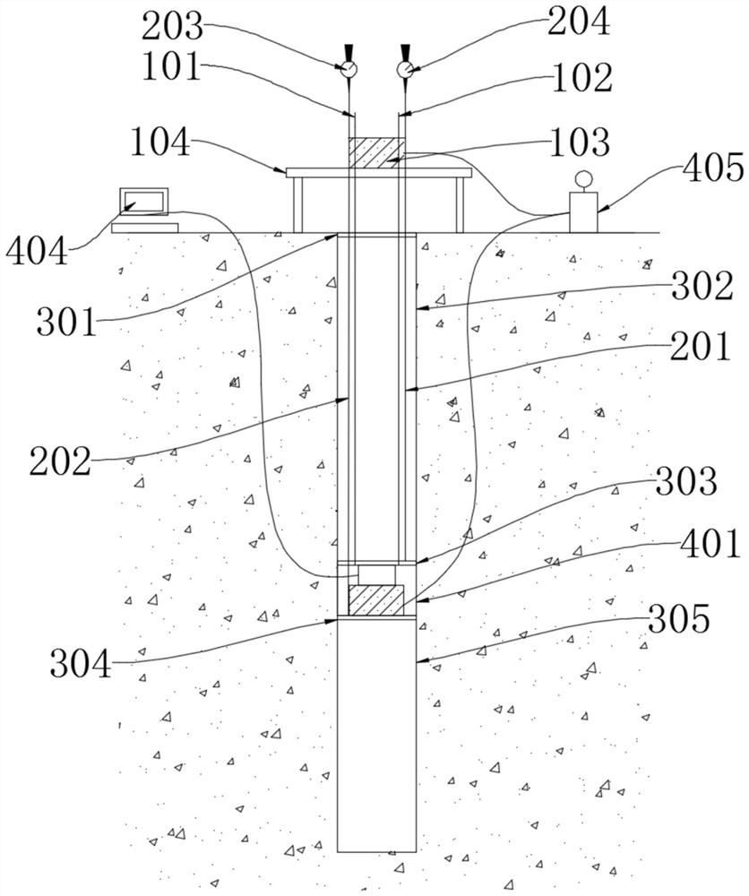
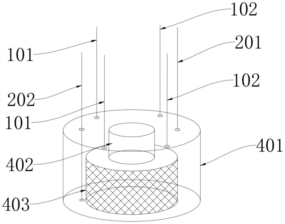
The invention discloses a pile foundation self-balancing test device with a balance point compensation function and a test method. The test device comprises an upper pile section, a lower pile section, a pile body jack, a pile pulling device and a displacement measurement device. According to the pile foundation self-balancing test device with the balance point compensation function and the test method, the pile body jack is arranged between the top of the lower pile section and the bottom of the upper pile section, and the pile body jack is started firstly; step-by-step load applying and graded loading are conducted through the pile body jack, real-time loads are recorded through a load sensor, and the displacement of the upper pile section and the displacement of the lower pile section are measured through the displacement measurement device; when the lower pile section reaches a limit state firstly, the pile pulling device is started to apply pile pulling force to the upper pile section until the upper pile section reaches the limit state; when the upper pile section reaches the limit state firstly, a counterweight test block is applied to the top of the upper pile section, then the pile body jack continues to be loaded until the lower pile section reaches the limit state, and the pile foundation bearing capacity is calculated according to the limit load of the upper pile section and the limit load of the lower pile section. According to the pile foundation self-balancing test device with balance point compensation function and test method, the problem that a balance point is inaccurate can be solved, and the pile foundation bearing capacity can be accurately calculated.
Description
technical field [0001] The invention belongs to the field of civil engineering, and relates to a self-balancing test pile technology, in particular to a pile foundation self-balancing test device and a test method with a balance point compensation function, which are used for the self-balancing test pile method to accurately measure the ultimate bearing capacity of pile foundations . Background technique [0002] The self-balancing pile test method utilizes the principle of the pile’s own reaction force balance. First, the self-balancing box of the pile body is pre-buried. During the test, the jack of the self-balancing box is used to apply load to the upper and lower piles, so that the upper section of the pile produces an upward displacement. Make the pile side frictional resistance reach the limit state; at the same time, exert downward pressure on the lower section of the pile, so that the lower section of the pile produces a downward displacement, so that the side frict...
Claims
Login to View More Application Information
Patent Timeline
 IPC IPC(8): E02D33/00
CPCE02D33/00
Inventor 刘永莉徐静肖衡林刘志杰李晨旭李丽华陈智
Owner HUBEI UNIV OF TECH
Features
- R&D
- Intellectual Property
- Life Sciences
- Materials
- Tech Scout
- Unparalleled Data Quality
- Higher Quality Content
- 60% Fewer Hallucinations
Learn More Browse by: Latest US Patents, China's latest patents, Technical Efficacy Thesaurus, Application Domain, Technology Topic, Popular Technical Reports.
© 2025 PatSnap. All rights reserved.Legal|Privacy policy|Modern Slavery Act Transparency Statement|Sitemap|About US| Contact US: help@patsnap.com


