
Pneumatic rotary damping device

A technology of rotating damping device and air chamber, which is applied to switches with brakes, door/window accessories, wing parts, etc., and can solve problems such as no damping

Pending Publication Date: 2021-11-05
WEIFANG ZHENGXIN PNEUMATIC TECH CO LTD
View PDF1 Cites 1 Cited by
  • Summary
  • Abstract
  • Description
  • Claims
  • Application Information

AI Technical Summary

Problems solved by technology

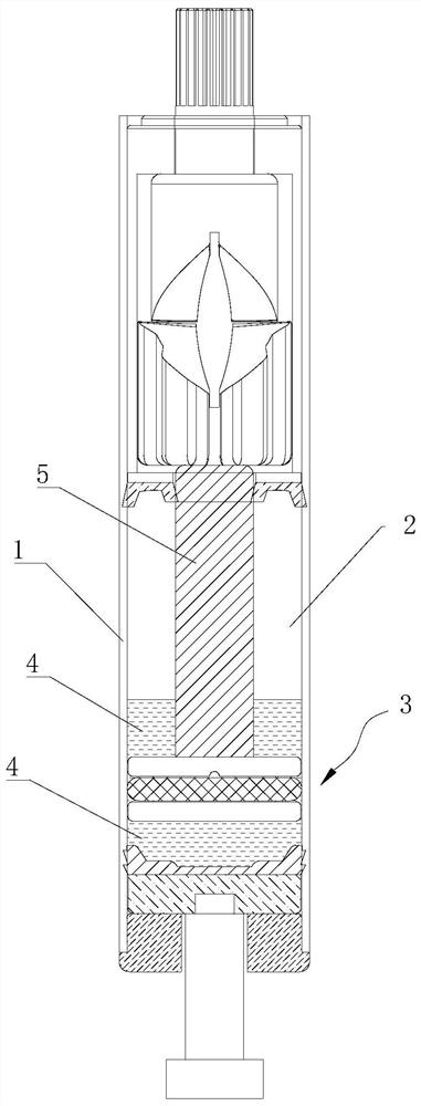
[0003] The invention proposes a pneumatic rotary damping device, which solves the problem of no damping of rotating parts such as doors or windows in the prior art

Method used


Image

  • Pneumatic rotary damping device
  • Pneumatic rotary damping device
  • Pneumatic rotary damping device

Examples


Embodiment 1

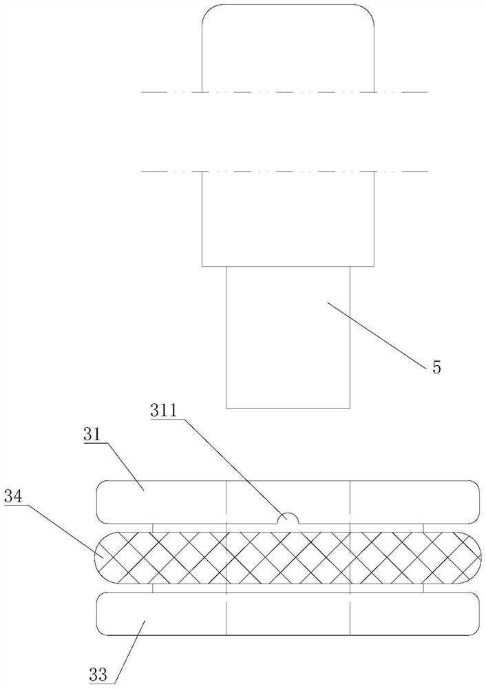
[0034] Such as image 3 and Figure 4 As shown, the piston 3 includes an upper end plate 31, a central column 32 and a lower end plate 33, and the piston 3 here is a split structure, namely Figure 5 As shown, the upper end plate 31 and the middle column 32 are fixed as one, and the lower end plate 33 is separately integrated, and the middle positions of the upper end plate 31, the middle column 32 and the lower end plate 33 are all provided with a through hole 35, and the lower end of the guide rod 5 Penetrating through the through hole 35 and sealingly fit with it.

[0035] The outer diameter of the middle column 32 is smaller than the outer diameter of the upper end plate 31 and the lower end plate 33, the piston 3 formed by the three is dumbbell-shaped, and the outer diameter of the upper end plate 31 and the lower end plate 33 is also smaller than the inner diameter of the airtight chamber 2, so that A gap is left between the upper end plate 31 and the airtight chamber ...

Embodiment 2

[0042] What the piston 3 in this embodiment adopts is Figure 6 In the one-piece structure shown, that is, the upper end plate 31 , the middle column 32 and the lower end plate 33 are fixed as a whole, and the rest of the structure is the same as that of Embodiment 1, and will not be repeated here.

Embodiment 3

[0044] The oil passing structure of the lower end plate 33 in this embodiment no longer adopts the second oil passing groove 331, but adopts Figure 10 As shown in the second oil hole 332, the number of the second oil hole 332 is at least two (three are shown in the figure), and these second oil holes 332 are evenly distributed on the lower end plate 33 in the circumferential direction, and the The second oil hole 332 penetrates the lower end plate 33 up and down, and is arranged in a misalignment with the O-ring 34 , that is, the second oil hole 332 is just located between the O-ring 34 and the center column 32 .

[0045] The rest of the structure of this embodiment is the same as that of Embodiment 1, and will not be repeated here.


PUM


Abstract

The invention provides a pneumatic rotary damping device. The problem that in the prior art, rotary parts such as doors or windows are not damped is solved. The pneumatic rotary damping device comprises a closed air chamber formed by a shell; a movable piston and grease are arranged in the closed air chamber; a guide rod is arranged in the middle of the piston in a sealing fit mode; the upper end of the guide rod extends out of the closed air chamber; and a grease passing structure for the grease to pass through is formed in the piston. The pneumatic rotary damping device is simple in overall structure and convenient to use, solves the problem that a rotary device has no damping, can achieve the purpose of controlling the rotary damping speed by changing the depth or diameter of the corresponding grease passing structure or the viscosity of the grease, and is suitable for various doors and windows and various occasions needing rotary damping.

Description

technical field [0001] The invention relates to the technical field of a pneumatic rotating device for doors and windows, in particular to a pneumatic rotating damping device which is simple in structure, easy to use and capable of providing damping for the rotating device. Background technique [0002] Floor springs and door closers are commonly used automatic return and door closing devices in the current market. The rotor and shaft in the pneumatic floor springs in the prior art are split structures. Compress and release the air pressure in the air chamber when returning to the position. Chinese invention patent CN113047719A discloses a pneumatic automatic return device, which uses the relative movement between the upper convex shaft and the lower convex shaft to compress the airtight air chamber, making it Large air pressure is formed inside, and when the door or window returns, the air pressure in the airtight air chamber is released, which can be adjusted according to ...

Claims


Application Information

Patent Timeline
Patent Type & Authority Applications(China)
IPC IPC(8): E05F3/04E05F3/02
CPCE05F3/04E05F3/02E05Y2900/132E05Y2900/148
Inventor 于宝峰司祥含
Owner WEIFANG ZHENGXIN PNEUMATIC TECH CO LTD
Learn More