
Differential pressure device capable of measuring and adjusting pressure and viscosity in real time and measuring method thereof

A viscosity and pressure technology, applied in the field of partial pressure injection devices, can solve the problems such as the inability to measure the pressure and viscosity of the solution, the unadjustable structure of the partial pressure injection tool, etc. Effect

Active Publication Date: 2019-10-25
NORTHEAST GASOLINEEUM UNIV
View PDF23 Cites 0 Cited by
  • Summary
  • Abstract
  • Description
  • Claims
  • Application Information

AI Technical Summary

Problems solved by technology

[0004] An object of the present invention is to provide a pressure dividing device that can measure and adjust the pressure and viscosity in real time. This pressure dividing device that can measure and adjust the pressure and viscosity in real time is used to solve the problem that the structure of the existing partial pressure injection tool cannot be adjusted and cannot be measured. The problem of pressure and viscosity when the solution flows through the partial pressure injection tool, another object of the present invention is to provide a method for measuring the pressure and viscosity of the partial pressure device that can be measured and adjusted in real time

Method used


Image

  • Differential pressure device capable of measuring and adjusting pressure and viscosity in real time and measuring method thereof
  • Differential pressure device capable of measuring and adjusting pressure and viscosity in real time and measuring method thereof
  • Differential pressure device capable of measuring and adjusting pressure and viscosity in real time and measuring method thereof

Examples


Embodiment Construction

[0042] Below in conjunction with accompanying drawing, the present invention will be further described:

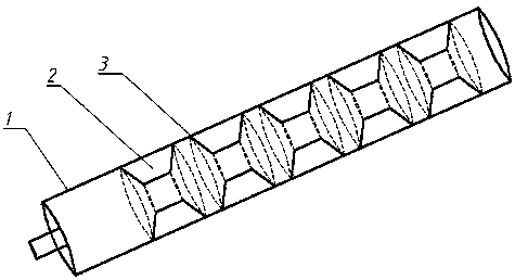
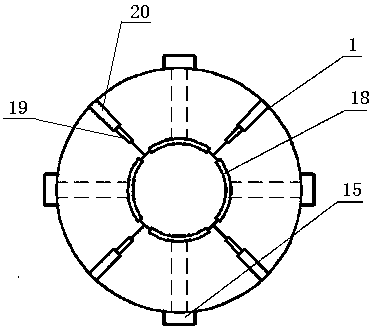
[0043] combine figure 1 , figure 2 , image 3As shown, the pressure dividing device that can measure and adjust the pressure and viscosity in real time includes an outer cylinder 1, an adjustable annular throttle groove 2, a viscosity meter, a pressure sensor 6, a current sensor 13, a torque sensor 14, an induction plate 5, and a DSP Control module 11, computer, 5 annular throttling grooves 2 are installed vertically on the inner wall of the outer cylinder 1 at equal intervals. A spontaneous viscometer, a pressure sensor 6, and a torque sensor 14 are installed on the launder 2, and are connected to the induction plate 5 through a transmission line 16. The induction plate 5 is provided with a microprocessor converter and a receiving transmitter, a pressure sensor 6, and a torque sensor 14. Both are connected with the induction board 5, the induction board 5 is connected...


PUM


Abstract

The invention relates to a differential pressure device capable of measuring and adjusting pressure and viscosity in real time and a measuring method thereof, wherein the differential pressure devicecapable of measuring and adjusting the pressure and viscosity in real time comprises an outer barrel and adjustable annular throttling troughs. The adjustable annular throttling troughs are installedon the inner wall of the outer barrel perpendicularly sequentially at equal intervals and are in a split type. A throttling trough single body is in an arc shape, and four throttling trough single bodies are arranged on one peripheral face concentrically in a two-two-adjacent mode to form one adjustable annular throttling trough. A viscosity meter is installed on the surface of an arc-shaped innerplate of the last adjustable annular throttling trough. The viscosity meter is connected with an induction plate through a transmission line. A pressure sensor and a torque sensor are installed on the arc-shaped inner plate of the last adjustable annular throttling trough and are both connected with the induction plate. The induction plate is connected with a DSP control module. Throttling differential pressure is changed by changing the annular throttling troughs of the differential pressure device, pressure of solution is adjusted, and meanwhile viscosity of the solution can also be changed.

Description

Technical field: [0001] The present invention relates to a partial pressure injection device used in stratified injection during oilfield development and production, in particular to a partial pressure device and a measuring method thereof which can measure and adjust pressure and viscosity in real time. Background technique: [0002] The main application objects of polymer flooding and other chemical flooding technologies mostly have problems such as strong heterogeneity of oil layers, many layers, and large differences between layers. The production degree of the low-permeability layer is low, which reduces the overall oil displacement effect. The layered injection process can alleviate the contradiction between layers, improve the injection profile, and improve the overall development effect. To achieve the above effects, it mainly depends on the throttling element in the partial pressure injection tool. Traditional throttling elements mainly include annular pressure-re...

Claims


Application Information

Patent Timeline
Patent Type & Authority Applications(China)
IPC IPC(8): E21B43/22E21B47/06G01N11/14G01L11/00
CPCE21B43/16E21B47/06G01N11/14G01L11/00G01N2011/147G01N2291/02818G01N2291/02872
Inventor 黄斌胡新宇戚向东傅程赵法军李晓慧逯春晶张伟文
Owner NORTHEAST GASOLINEEUM UNIV
Learn More