Overflow valve and engineering machinery with same

A relief valve and spool technology, applied in the field of hydraulic components, can solve problems such as difficult production efficiency and operability, prolonging the transition time when starting and accelerating and decelerating and stopping, and reducing the production efficiency of excavators.

Pending Publication Date: 2021-11-05
SUOTE TRANSMISSION EQUIP
View PDF0 Cites 0 Cited by
  • Summary
  • Abstract
  • Description
  • Claims
  • Application Information

AI Technical Summary

Problems solved by technology

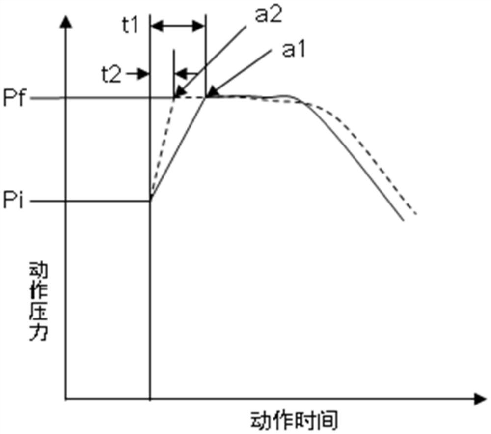
In mode a1, the buffer time is longer, which can reduce the impact of deceleration and stop, but prolongs the transition time between startup and acceleration and deceleration and stop, which will reduce the production efficiency of the excavator
However, in mode a2, the buffer time is short, and the impact d

Method used


Image

  • Overflow valve and engineering machinery with same
  • Overflow valve and engineering machinery with same
  • Overflow valve and engineering machinery with same

Examples


Embodiment Construction

[0026] The technical solutions of the present invention will be clearly and completely described below in conjunction with the accompanying drawings. Apparently, the described embodiments are some of the embodiments of the present invention, but not all of them. Based on the embodiments of the present invention, all other embodiments obtained by persons of ordinary skill in the art without making creative efforts belong to the protection scope of the present invention.

[0027] In the description of the present invention, it should be noted that the terms "center", "upper", "lower", "left", "right", "vertical", "horizontal", "inner", "outer" etc. The indicated orientation or positional relationship is based on the orientation or positional relationship shown in the drawings, and is only for the convenience of describing the present invention and simplifying the description, rather than indicating or implying that the referred device or element must have a specific orientation, ...


PUM


Abstract

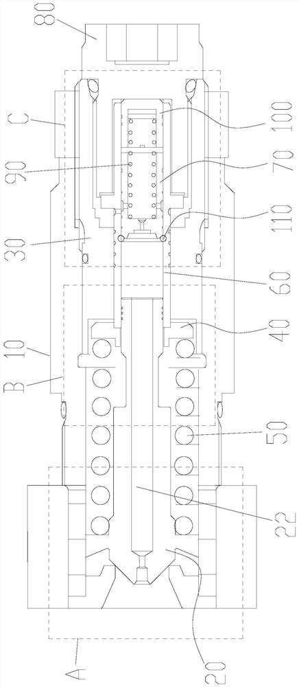
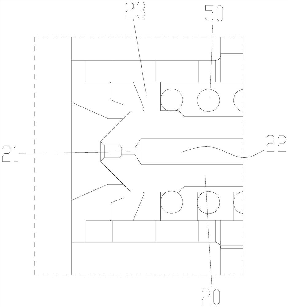
The invention provides an overflow valve and engineering machinery with the same. The overflow valve comprises a valve body, a first valve core, an adjusting sleeve, a spring seat, a first elastic piece, a valve sleeve, a second valve core, a plug and a second elastic piece. According to the overflow valve, by setting the rated load and the elastic constant of the second elastic piece, the characteristic of a boosting mode a3 can be realized, the set pressure during acceleration starting and deceleration stop is further improved from the conventional Pf to Ph, the characteristics of acceleration starting and deceleration stop are improved, and the production efficiency is improved. Besides, the moving time of the valve sleeve is prolonged so that the boosting mode during operation is more stable, the impact is reduced, and the operability of a hydraulic excavator is improved. According to the technical scheme, the defect that in the prior art, the overflow valve is difficult to consider production efficiency and operability at the same time is overcome.

Description

technical field [0001] The invention relates to the technical field of hydraulic components, in particular to an overflow valve and construction machinery with the same. Background technique [0002] The relief valve is mainly used for actuators with large rotary inertia such as hydraulic excavators. The general working process of the relief valve in the prior art is that the high-pressure oil pushes the spool open through the high-pressure port to overflow at a lower pressure, and another part of the high-pressure oil flows into the rightmost end of the spool shaft through the inner cavity of the spool. The high-pressure oil flows through the holes and grooves on the side wall of the spool, and flows into the oil chamber through the annular throttling passage, and the pressure oil flowing into the oil chamber further flows into the oil chamber through the holes. The pressure oil pushes the spring seat to compress the spring in the oil chamber, so that the pressure of the r...

Claims


Application Information

Patent Timeline
IPC IPC(8): F15B13/02F15B21/00
CPCF15B13/02F15B21/00
Inventor 松本哲王鹏徐浩祯于晓晨
Owner SUOTE TRANSMISSION EQUIP
Why Eureka
Try Eureka