Method and system for realizing inertial space scanning imaging

An inertial space, scanning imaging technology, applied in the field of inertial space scanning imaging, to achieve the effect of small gyro drift and stable gyro speed control

Pending Publication Date: 2021-11-05
湖南宏动光电有限公司
View PDF0 Cites 0 Cited by
  • Summary
  • Abstract
  • Description
  • Claims
  • Application Information

AI Technical Summary

Problems solved by technology

[0005] The present invention provides a method and system for realizing inertial space scanning imaging, aiming to solve the technical problems of existing defects in inertial space scanning imaging

Method used


Image

  • Method and system for realizing inertial space scanning imaging
  • Method and system for realizing inertial space scanning imaging
  • Method and system for realizing inertial space scanning imaging

Examples


Embodiment Construction

[0062] In order to better understand the above-mentioned technical solution, the above-mentioned technical solution will be described in detail below in conjunction with the accompanying drawings and specific implementation methods.

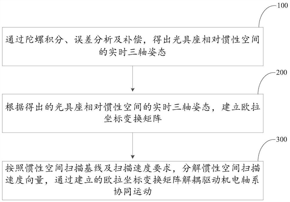
[0063] like figure 1 and figure 2 As shown, the first embodiment of the present invention proposes a method for realizing inertial space scanning imaging, including the following steps:

[0064] Step S100, through gyro integration, error analysis and compensation, obtain the real-time three-axis attitude of the optical bench relative to the inertial space.

[0065] Through gyro integration, error analysis and compensation, and drift correction with the help of Beidou and inclinometers, the three-axis attitude of the optical bench relative to the inertial space can be obtained. Small inertial navigation components can also be used to measure the attitude angle of the photoelectric system.

[0066] Step S200 , according to the obtained real-time...


PUM


Abstract

The invention discloses a method and system for realizing inertial space scanning imaging. The method for realizing inertial space scanning imaging comprises the following steps of: obtaining a real-time three-axis attitude of an optical bench relative to an inertial space through gyro integration, error analysis and compensation; establishing an Euler coordinate transformation matrix according to the obtained real-time three-axis attitude of the optical bench relative to the inertial space; and according to an inertial space scanning baseline and a scanning speed requirement, decomposing an inertial space scanning speed vector, and performing decoupling through the established Euler coordinate transformation matrix so as to drive an electromechanical shafting system to move cooperatively . According to the method and the system for realizing inertial space scanning imaging provided by the invention, the search scanning of the inertial space stable baseline is realized, a gyroscopic drift is small, and the gyroscopic speed control is stable.

Description

technical field [0001] The invention relates to the technical field of photoelectric imaging, and in particular discloses a method and system for realizing inertial space scanning imaging. Background technique [0002] Inertial space can be understood as cosmic space. Since the universe is infinite, it is meaningful to describe the movement relative to inertial space with specific reference objects. That is to find objects in the cosmic space with no force or force and the resultant force is zero. They remain absolutely static or move in a straight line at a uniform speed in the inertial space. The frame of reference constituted by them is the inertial frame of reference. [0003] In the prior art, to achieve inertial space scanning and imaging, a three-axis fiber optic gyro is generally used to control a three-axis servo turntable to achieve stable scanning in inertial space, but the core problems are: 1. Signal amplification and transformation in complex noise environments...

Claims


Application Information

Patent Timeline
Patent Type & Authority Applications(China)
IPC IPC(8): G01B11/24G01B11/00G01C21/18G01C21/16G01C25/00
CPCG01B11/2433G01B11/002G01C21/18G01C21/183G01C21/165G01C25/005
Inventor 周欢喜杨俊波贾红辉
Owner 湖南宏动光电有限公司
Why Eureka
Try Eureka