
Chiral fluorescence confocal imaging system and imaging method

An imaging system, confocal technology, applied in the field of optics, achieves the effects of saving economic costs, improving imaging resolution, and simplifying the imaging optical system

Inactive Publication Date: 2021-11-05
INST OF CHEM CHINESE ACAD OF SCI
View PDF6 Cites 0 Cited by
  • Summary
  • Abstract
  • Description
  • Claims
  • Application Information

AI Technical Summary

Problems solved by technology

However, in the field of microscopy imaging, there is a lack of imaging instruments for the study of chiral fluorescence

Method used


Image

  • Chiral fluorescence confocal imaging system and imaging method

Examples


Embodiment Construction

[0030] The following will clearly and completely describe the technical solutions in the embodiments of the present invention with reference to the accompanying drawings in the embodiments of the present invention. Obviously, the described embodiments are only part of the embodiments of the present invention, not all of them. Based on the embodiments of the present invention, all other embodiments obtained by persons of ordinary skill in the art without creative efforts fall within the protection scope of the present invention.

[0031] It should be noted that all directional indications (such as up, down, left, right, front, back...) in the embodiments of the present invention are only used to explain the relationship between the components in a certain posture (as shown in the accompanying drawings). Relative positional relationship, movement conditions, etc., if the specific posture changes, the directional indication will also change accordingly.

[0032] In addition, in t...


PUM


Abstract

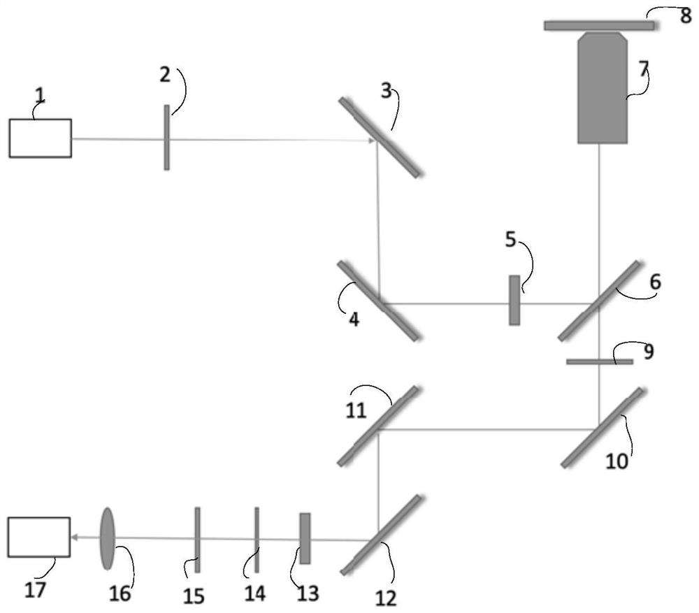
The invention relates to the technical field of optics, and particularly discloses a chiral fluorescence confocal imaging system and method. The chiral fluorescence confocal imaging system comprises a laser device, an excitation light path, a microscope, a sample table, a detection light path, a photoelectric detector and a control device, wherein laser emitted by the laser device is modulated by the excitation light path to generate polarized light, the polarized light irradiates a to-be-detected sample on the sample table through the microscope and excites the to-be-detected sample to generate a fluorescence signal, the fluorescence signal is modulated by the detection light path and transmitted to the photoelectric detector, the photoelectric detector converts the fluorescence signal into an electric signal and forms an image, and the control device is connected with the photoelectric detector and the sample table. According to the chiral fluorescence confocal imaging system, the imaging resolution of a traditional optical microscope can be improved, and laser confocal imaging is achieved.

Description

technical field [0001] The invention relates to the field of optical technology, and specifically discloses a chiral fluorescence confocal imaging system and an imaging method. Background technique [0002] Laser scanning confocal microscope (Laser scanning confocal microscope) is a new technology developed in the mid-1980s and widely used. The advanced cell and molecular biology analysis instruments produced by the combination are more and more widely used in the fields of biology and medicine, and have become an essential tool for biomedical experimental research. [0003] Traditional fluorescence microscopes use fluorescent substances to mark specific structures in cells, which not only enhances the contrast between the image and the background, but also greatly improves the resolution (δ=0.61·λ / NA, where δ is the resolution of the microscope; λ is the wavelength of the illumination light; NA is the numerical aperture of the objective lens). However, when the observed f...

Claims


Application Information

Patent Timeline
Patent Type & Authority Applications(China)
IPC IPC(8): G01N21/64G01N21/01
CPCG01N21/64G01N21/01
Inventor 袁景和岑柏桦方晓红
Owner INST OF CHEM CHINESE ACAD OF SCI
Learn More