Escape-proof control adjustable fishing tool
An adjustable and anti-escape technology, which is applied in the field of fishing equipment, can solve the problems of high labor intensity, inability to adjust the angle of entry into the water of the net bag, and high technical difficulty, and achieve the effects of preventing secondary escape, ingenious structure, and easy fishing operation
- Summary
- Abstract
- Description
- Claims
- Application Information
AI Technical Summary
Problems solved by technology
Method used
Image
Examples
Embodiment 1
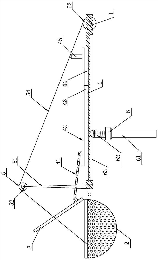
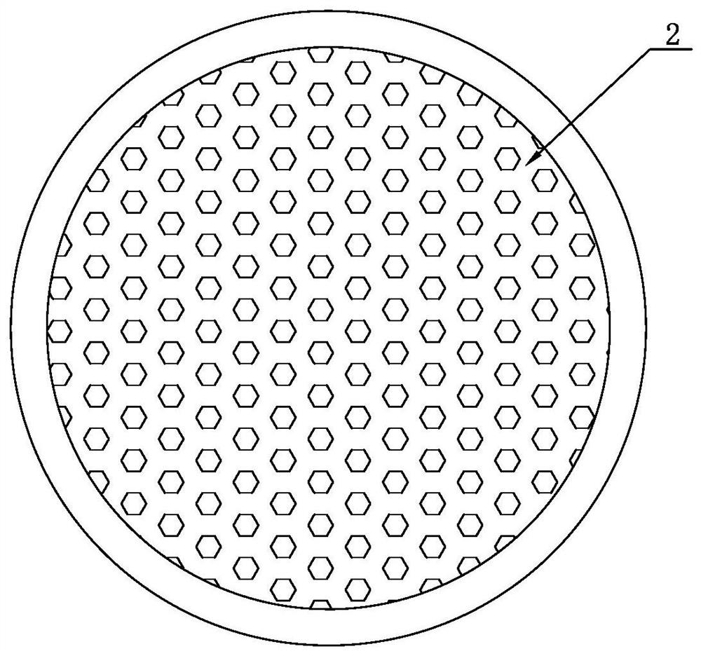
[0027] An anti-escape control adjustable fishing tackle, such as figure 1 , image 3 Shown, comprise support bar 1 and net bag 2, and net bag 2 is arranged on an end of support bar 1, and support bar 1 is hingedly connected with net bag 2, is provided with anti-escape net cover 3 on net bag 2, in anti-escape net cover 3 and support A net cover control mechanism 4 is provided between the bars 1, a net bag inclination control mechanism 5 is provided between the net bag 2 and the support bar 1, and a support mechanism 6 is provided on the lower end surface of the support bar 1;
[0028] Described net cover control mechanism 4 comprises connecting rod 41, moving bar 42, sliding block 43, upper sliding groove 44 and handle 45, and upper sliding groove 44 is arranged on the upper end surface of support rod 1, and along the support rod 1 The length direction of the rod body is arranged, and the sliding block 43 is fixed on the lower end surface of the moving rod 42, and the sliding ...
Embodiment 2
[0031] Embodiment 2: It is different from Embodiment 1 in that: the support mechanism 6 also includes an adjustment wheel 64, the ball bearing rod 62 is a screw structure, and the center of the adjustment wheel 64 is provided with a threaded hole corresponding to the ball bearing rod 62, The supporting frame 61 is a column tube structure with an internal threaded hole, and the ball bearing rod 62 is screwed into the internal threaded hole of the column tube and locked by the locking adjustment wheel 64 .
Embodiment 3
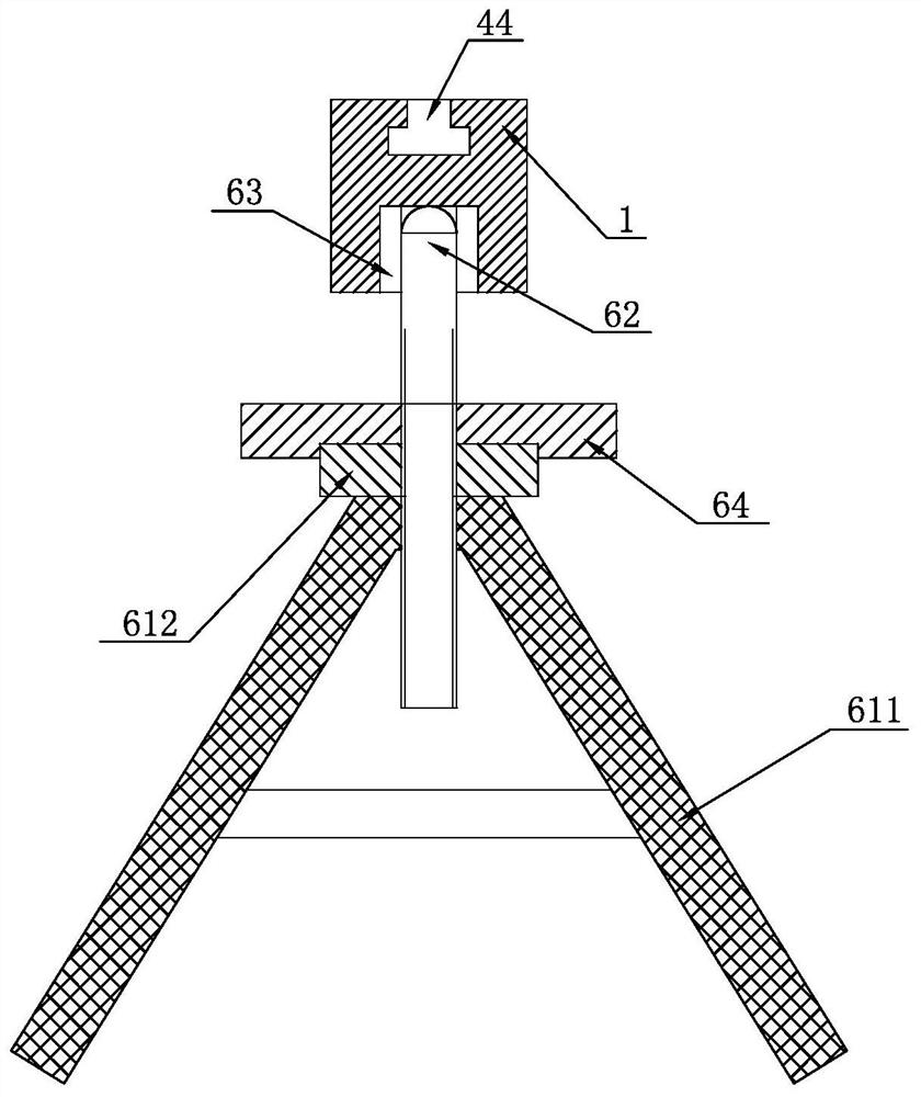
[0032] Embodiment 3: The difference from Embodiment 1 is that the carrier frame 61 is a tripod structure, such as figure 2 As shown, it includes three supporting legs 611 and a bearing plate 612 arranged on the top of the tripod. The center of the bearing plate 612 is provided with a through hole or a threaded inner hole. The ball bearing rod 62 is screwed into the threaded hole of the adjustment wheel 64, and A through hole or a threaded inner hole is located at the center of the supporting plate 612 .
PUM
 Abstract
Description
Claims
Application Information
 - R&D
- Intellectual Property
- Life Sciences
- Materials
- Tech Scout
- Unparalleled Data Quality
- Higher Quality Content
- 60% Fewer Hallucinations
Browse by: Latest US Patents, China's latest patents, Technical Efficacy Thesaurus, Application Domain, Technology Topic, Popular Technical Reports.
© 2025 PatSnap. All rights reserved.Legal|Privacy policy|Modern Slavery Act Transparency Statement|Sitemap|About US| Contact US: help@patsnap.com


