
Horizontal type rotational flow plate liquid exhauster

A swirl plate and deliquoring technology, applied in the field of horizontal swirl plate deliquor, can solve the problems of falling in the middle of the cylinder, secondary escape of sedimentary water, and reducing enterprise efficiency.

Inactive Publication Date: 2021-07-06
南通海鹰机电集团有限公司
View PDF2 Cites 0 Cited by
  • Summary
  • Abstract
  • Description
  • Claims
  • Application Information

AI Technical Summary

Problems solved by technology

Although adding a guide cone in the middle of the swirl plate can increase the transportation distance of the gas to a certain extent, there is still no structure on the guide cone that can further accelerate the gas, and after the gas enters the cylinder, it will Slight liquid, there is no water-retaining structure at the bottom of the cylinder to prevent the contact between the liquid and the inner wall of the cylinder
[0005] In summary, the existing disclosed dehydrator device will drop in the middle of the cylinder or fail to reach the end of the cylinder when the gas power of the impurity gas is insufficient, and in the case of liquid dripping If there is no water-retaining measure, the rotating flow of the air flow will cause the second escape of the deposited water, which will seriously affect the production and reduce the efficiency of the enterprise

Method used


Image

  • Horizontal type rotational flow plate liquid exhauster
  • Horizontal type rotational flow plate liquid exhauster
  • Horizontal type rotational flow plate liquid exhauster

Examples


Embodiment Construction

[0019] In order to deepen the understanding of the present invention, the specific implementation of the present invention will be described in detail below in conjunction with the accompanying drawings. This embodiment is only used to explain the present invention and does not constitute a limitation to the protection scope of the present invention.

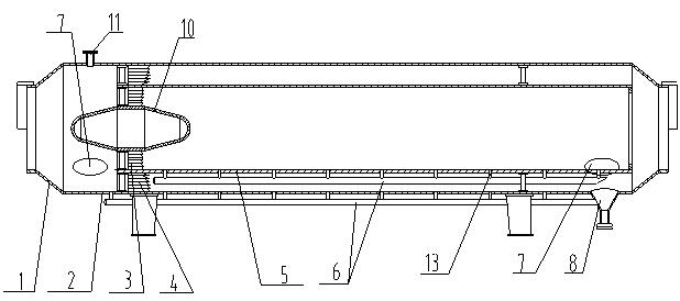
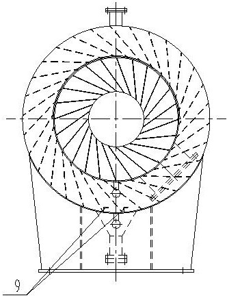
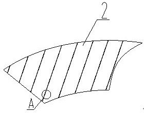
[0020] Such as Figure 1-4 As shown, the horizontal swirl plate deliquifier includes a conical tube 1 and a cylinder body 2, the conical tube 1 is located at both ends of the cylinder body 2, a diversion cone 10 is provided in the middle of one end of the conical tube 2, and the top of the cylinder body 2 is provided with Vent port 11, the vent port 11 vents the gas or liquid inside the dehydrator, and the two ends of the cylinder 7 are provided with manholes 7, and the manholes 7 are used for pressure relief when the internal pressure of the dehydrator increases sharply. The diversion cone 10 is olive-shaped or streamlined, and...


PUM


Abstract

The invention discloses a horizontal type rotational flow plate liquid exhauster which comprises taper pipes and a barrel, the taper pipes are located at the two ends of the barrel, a flow guide cone is arranged in the middle of one end of each taper pipe, rotational flow pieces are arranged on the two sides of each flow guide cone, regular riflings are arranged on the surfaces of the flow guide cones and the rotational flow pieces, and the rotational flow pieces comprise inner rotational flow pieces and outer rotational flow pieces. A liquid blocking ring is arranged between the inner rotational flow pieces and the outer rotational flow pieces, the outer rotational flow pieces are located between the liquid blocking ring and the barrel, and a water blocking ring is arranged on the side wall, at the rear side of the outer rotational flow pieces, of the barrel. A water retaining liquid ring is used for preventing secondary escape of deposited water caused by rotational flowing of air flow. A water collecting pipe can timely drain water at the bottom of the water blocking ring. The regular riflings are designed on the surfaces of the flow guide cones and a rotational flow plate, so that the speed and direction of airflow are suddenly changed, the vortex effect is greatly enhanced, and liquid drops flow downwards along the rotational flow plate and the barrel wall, settle and converge at the bottom of the liquid exhauster and are finally discharged from a water outlet through the water collecting pipe. Accumulation and corrosion of impurities on the side wall are effectively avoided.

Description

technical field [0001] The invention relates to the field of gas dehydration and dust removal, in particular to a horizontal swirl plate dehydrator. Background technique [0002] The dehydration and dust removal of the front-end process is not ideal. The water content and dust content in the process pipeline gas are high. The high content of sulfur and phosphorus in raw materials such as coal and iron ore leads to high content of sulfur oxides and phosphorus oxides in the gas, which dissolve in water vapor to form acidic corrosion media that corrode the inner wall of the pipeline. The corroded scale of the pipeline along the line peels off along with the movement of the gas flow and water flow and deposits at the resistance. Where the gas pipeline leads to the user, the large-diameter gas pipeline is divided into several small-diameter pipelines, and the local resistance at the small pipe increases, resulting in the deposition of impurities. Due to the acidity of the impur...

Claims


Application Information

Patent Timeline
Patent Type & Authority Applications(China)
IPC IPC(8): C10K1/02C10K1/00
CPCC10K1/002C10K1/026
Inventor 杨裕能俞金芳陈建忠
Owner 南通海鹰机电集团有限公司
Learn More