
Beverage production device

A technology for producing equipment and beverages, which is applied in the directions of dissolving, mixer, and food forming, etc., can solve the problem of not being able to stack raw materials, and achieve the effect of improving processing efficiency, improving direction and method, and speeding up mixing speed.

Active Publication Date: 2021-11-09
广东焕然生物科技有限公司
View PDF10 Cites 2 Cited by
  • Summary
  • Abstract
  • Description
  • Claims
  • Application Information

AI Technical Summary

Problems solved by technology

[0005] Aiming at the deficiencies of the prior art, the present invention provides a beverage production device, which solves the problem that the existing beverage production equipment cannot pile up raw materials during processing, avoids the raw materials being easily squeezed to the corners and reduces the The number of times of processing increases the direction and method of processing, improves the efficiency of beverage processing, avoids the adhesion of raw materials to the inner wall of the device, and improves the utilization of raw materials

Method used


Image

  • Beverage production device
  • Beverage production device
  • Beverage production device

Examples


Embodiment 1

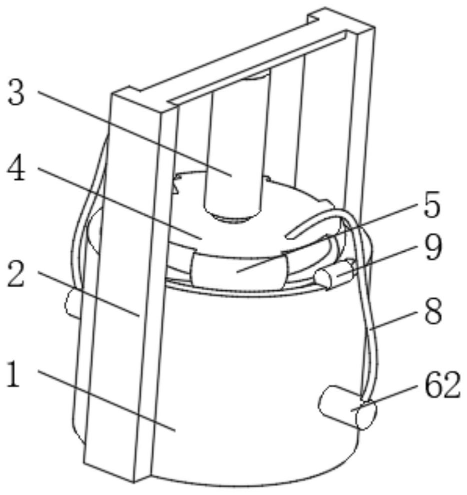
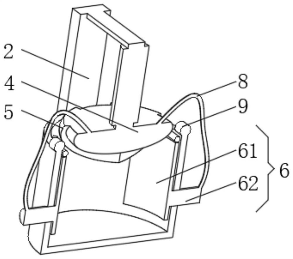
[0033] see Figure 1-4 , the present invention provides a technical solution: a beverage production device, including a processing barrel 1, a mounting frame 2 is installed on the outside of the processing barrel 1, a processing oil cylinder 3 is fixedly connected to the inner bottom of the mounting frame 2, and one end of the bottom of the processing oil cylinder 3 The processing block 4 is connected in rotation, and the outside of the processing block 4 is installed with:

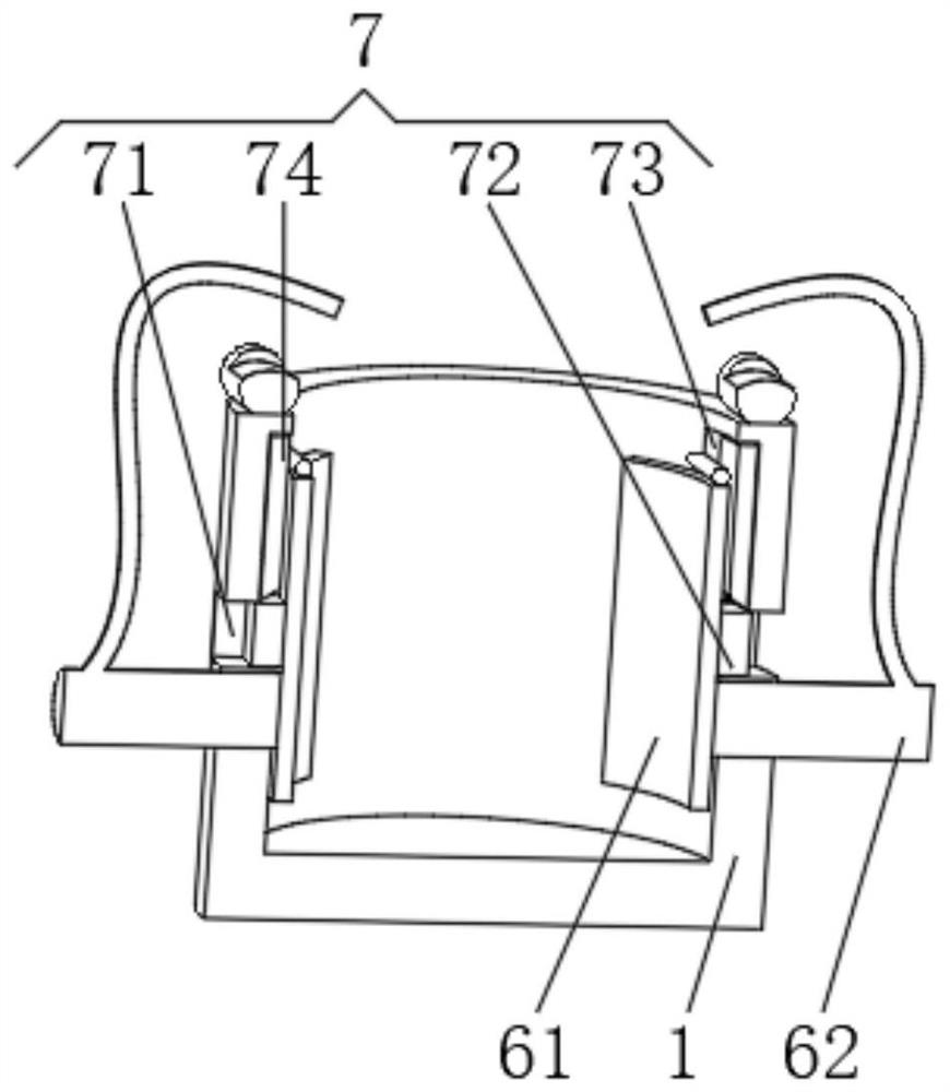
[0034] Stacking device 6, the stacking device 6 has a swing plate 61, the swing plate 61 is the same as the inner wall radian of the processing barrel 1, a push rod 62 is installed on one side of the swing plate 61, and the push rod 62 runs through the processing barrel 1 and extends to the processing barrel 1. the exterior of bucket 1;

[0035] Inflatable device 7, the inflatable device 7 has an inflation hole 71, one side of the swing plate 61 is fixedly connected with a sealing protrusion 72 suitable ...

Embodiment 2

[0040] see Figure 1-6 , the present invention provides a technical solution: on the basis of Embodiment 1, a side cutting device 5 is installed on the outside of the processing block 4, the side cutting device 5 has a backing plate 51, and the bottom of the backing plate 51 is equipped with a guide plate through an elastic plate 52 53 , a guide spring 54 is fixedly connected between the backing plate 51 and the guide plate 53 , and a side cutting sawtooth piece 55 is fixedly connected to one side of the backing plate 51 .

[0041] The top of the guide plate 53 is fixedly connected with a tilting rod 10 , and the end of the tilting rod 10 away from the guide plate 53 is fixedly connected with a booster plate 11 .

[0042] A stirring tank 12 is provided on the side of the sealing protrusion 72 far away from the swing plate 61 , a stirring rod 13 is mounted inside the stirring tank 12 , and a stirring blade 14 is mounted on one end of the stirring rod 13 .

[0043] One side of ...


PUM


Abstract

The invention discloses a beverage production device, which comprises a processing barrel; a mounting frame is mounted outside the processing barrel; a processing oil cylinder is fixedly connected to the bottom of the inner side of the mounting frame; a processing block is rotationally connected to one end of the bottom of the processing oil cylinder; a side cutting device, a gathering and stacking device and an air charging device are installed outside the processing block; the side cutting device is provided with a base plate; a guide plate is mounted at the bottom of the base plate through an elastic plate; the gathering and stacking device is provided with a swinging plate; the radian of the swinging plate is the same as that of the inner wall of the processing barrel; and the air charging device is provided with an air charging hole. The invention relates to the technical field of beverage preparation. According to the beverage production device, the purpose of gathering and stacking raw materials in the processing process is achieved; the problem that the processing frequency is reduced due to the fact that the raw materials are easily extruded to corners is solved; the processing direction and mode are increased; the beverage processing efficiency is improved; the raw materials can be prevented from being attached to the inner wall of the device; and the utilization rate of the raw materials is improved.

Description

technical field [0001] The invention relates to the technical field of beverage preparation, in particular to a beverage production device. Background technique [0002] Beverage production equipment refers to the equipment used to manufacture various beverages, generally composed of many equipment production lines to process various beverages, such as water treatment equipment, bottle rinsing machines, filling machines, sealing machines, sterilization equipment, CIP cleaning machines, filtration equipment, packaging equipment, etc. [0003] However, the existing beverage production equipment cannot pile up the raw materials during the processing, the raw materials are easily squeezed to the corners to reduce the number of times of processing, the processing direction and method are single, the processing efficiency is low, and the raw materials are easy to adhere to The inner wall of the device reduces the utilization efficiency of raw materials. Contents of the inventio...

Claims


Application Information

Patent Timeline
Patent Type & Authority Applications(China)
IPC IPC(8): A23P30/00A23L2/00A23L2/70B01F13/02B01F13/10B01F33/40
CPCA23P30/00A23L2/00A23L2/70
Inventor 梁忍
Owner 广东焕然生物科技有限公司
Learn More