
Protective device for clinical use in pneumology department

A protective device and clinical technology, applied in the field of medical equipment, can solve the problems of inconvenient movement, large size, inconvenient transportation, etc., and achieve the effect of avoiding cross-infection and good epidemic prevention effect

Inactive Publication Date: 2021-11-09
ZHENGZHOU UNIV
View PDF6 Cites 0 Cited by
  • Summary
  • Abstract
  • Description
  • Claims
  • Application Information

AI Technical Summary

Problems solved by technology

[0003] At present, the existing protective devices for respiratory clinical use are usually isolated by glass, but the glass is fixed on the sitting table, which is large in size and inconvenient to move and transport.

Method used


Image

  • Protective device for clinical use in pneumology department
  • Protective device for clinical use in pneumology department
  • Protective device for clinical use in pneumology department

Examples


Embodiment 1

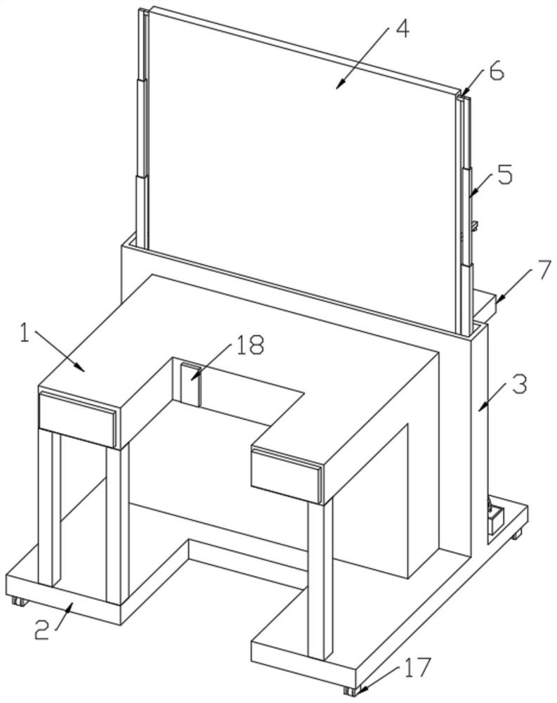
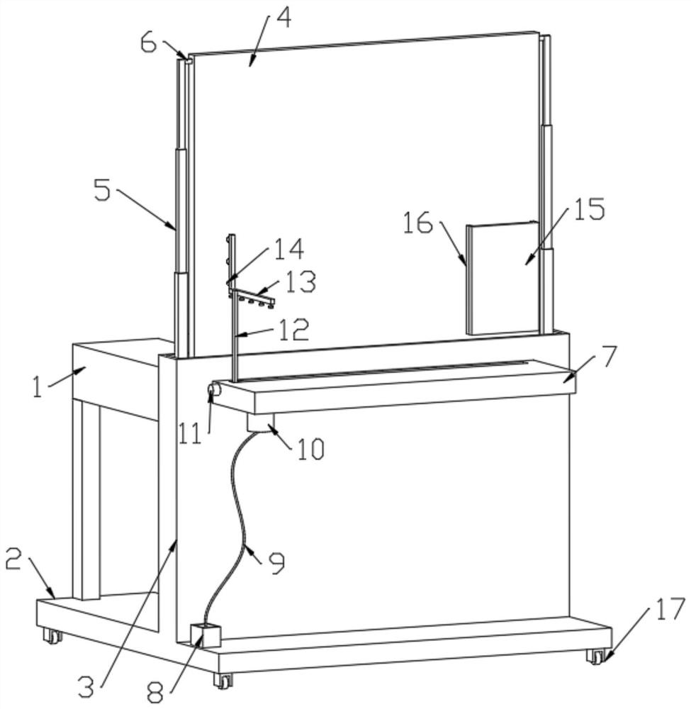
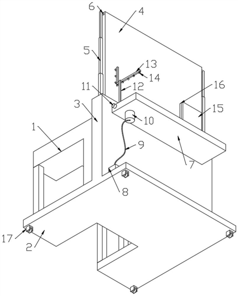
[0030] Depend on Figure 1-Figure 6 Given, a protective device for clinical use in respiratory department, including a consultation table 1, a storage box 3 is fixedly connected to one side of the consultation table 1, a screw rod b24 is rotatably connected to the storage box 3, and a driving motor is arranged in the consultation table 1 b21, the driving motor b21 is connected with the screw rod b24 through the linkage device, the screw rod b24 is connected with the lifting plate 28 through the connecting device, the side wall of the lifting plate 28 is slidingly connected with the inner side wall of the storage box 3, and the top of the lifting plate 28 is fixedly connected with Isolation glass 4;

[0031] A controller 18 is fixedly connected to the consultation table 1, and the controller 18 is electrically connected to the driving motor b21.

[0032] The storage box 3 is used to store the insulating glass 4 .

[0033] The linkage device includes a sprocket 22 fixedly conn...

Embodiment 2

[0045]On the basis of Embodiment 1, the side of the storage box 3 away from the consultation table 1 is fixedly connected with a fixed plate 7, and the fixed plate 7 is provided with a movable moving block a19, and the top of the moving block a19 is fixedly connected with a support rod 12, The top of the support rod 12 is fixedly connected with an L-shaped bracket 13, the outer wall of the L-shaped bracket 13 is fixedly connected with a plurality of nozzles 14, the bottom of the fixed plate 7 is fixedly connected with a delivery pump 10, and the output end of the delivery pump 10 is connected to the A plurality of spray heads 14 are connected, and a container 8 is arranged under the fixed plate 7 , and the container 8 is connected to the input end of the delivery pump 10 through a connecting pipe 9 .

[0046] The effect of moving block a19 is to facilitate the movement of the position of L-shaped support 13, so that the sprinkler head 14 installed on the L-shaped support 13 ste...


PUM


Abstract

The invention discloses a protective device for clinical use in the pneumology department, and relates to the technical field of medical instruments. The protective device comprises a sitting diagnosis table, one side of the sitting diagnosis table is fixedly connected with a storage box, the storage box is internally and rotatably connected with a lead screw b, the sitting diagnosis table is internally provided with a driving motor b, the driving motor b is connected with the lead screw b through a linkage device, and the lead screw b is connected with a lifting plate through a connecting device. According to the device, through the cooperation effect of the driving motor b, the lead screw b, the linkage device, the connecting rod, a moving block b, a U-shaped block and a rotating shaft, the driving motor b rotates to drive the lead screw b to rotate in a storage box, the position of the moving block b is adjusted, when the position of the moving block b on the lead screw b is changed, the inclination angle of the connecting rod is changed, therefore, the effect of lifting the lifting plate is achieved, the function of lifting isolation glass is achieved, and the size of the clinical protection device for the pneumology department can be shrunk conveniently.

Description

technical field [0001] The invention relates to the technical field of medical devices, in particular to a protective device for clinical use in respiratory department. Background technique [0002] Lin: face, to the meaning; bed: hospital bed. Clinical literally means to go to the hospital bed, or approach the patient, and generally refers to the person who directly contacts the patient and gives diagnosis and treatment. Such as clinical departments (internal medicine, surgery, operating room), clinical nurses, clinicians, clinicians. The Department of Respiratory Medicine is divided into Respiratory Medicine and Respiratory Surgery. Respiratory Surgery is responsible for lung and large airway surgery (such as lung tumors, pulmonary lobectomy, etc.). Lower respiratory tract and lung diseases that are mainly treated with drugs are managed by the Department of Respiratory Medicine. Clinicians in the respiratory department of the hospital are in contact with patients with a ...

Claims


Application Information

Patent Timeline
IPC IPC(8): A47B37/00A47B91/06A61L2/18A61L2/24A61L2/26G02B27/02
CPCA47B37/00A47B91/06A61L2/18A61L2/24A61L2/26G02B27/024A61L2202/14
Inventor 闫书铭
Owner ZHENGZHOU UNIV
Learn More