A driving device for adjusting the spatial position of an ultrasonic probe

A driving device and space position technology, applied in the field of ultrasonic diagnosis, can solve the problems of angle and distance deviation, angle and front-back distance not meeting the requirements of medical staff, increasing the workload of medical staff, etc.

Active Publication Date: 2021-12-24
广东恒腾科技有限公司
View PDF9 Cites 0 Cited by
  • Summary
  • Abstract
  • Description
  • Claims
  • Application Information

AI Technical Summary

Problems solved by technology

[0003] The existing ultrasonic testing equipment realizes the adjustment of various angles and front and rear distances of the ultrasonic probe through the control system to control various mechanisms. Although the existing ultrasonic testing equipment has realized automation, due to the programmed control, the ultrasonic testing equipment The flexibility of probe control is low, so that the adjusted angle and distance of the probe cannot meet the requirements of the medical staff, and there is a certain deviation from the angle and distance that the medical staff thinks, so that the medical staff needs to constantly check during the detection process. Manipulate automatic detection equipment to obtain the desired angle and moving distance
[0004] Moreover, the display screen of the ultrasonic testing equipment is placed in other positions, requiring medical staff to operate the testing equipment while observing the display screen and observing the patient's condition from time to time, thereby increasing the workload of the medical staff during the ultrasonic testing process

Method used


Image

  • A driving device for adjusting the spatial position of an ultrasonic probe
  • A driving device for adjusting the spatial position of an ultrasonic probe
  • A driving device for adjusting the spatial position of an ultrasonic probe

Examples


Embodiment Construction

[0040] The following will clearly and completely describe the technical solutions in the embodiments of the present invention with reference to the accompanying drawings in the embodiments of the present invention. Obviously, the described embodiments are only some, not all, embodiments of the present invention. Based on the embodiments of the present invention, all other embodiments obtained by persons of ordinary skill in the art without making creative efforts belong to the protection scope of the present invention.

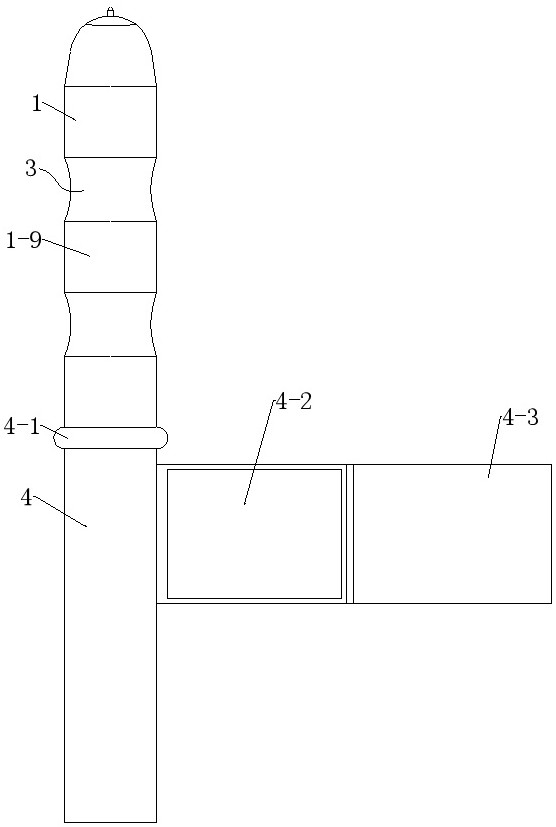
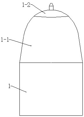
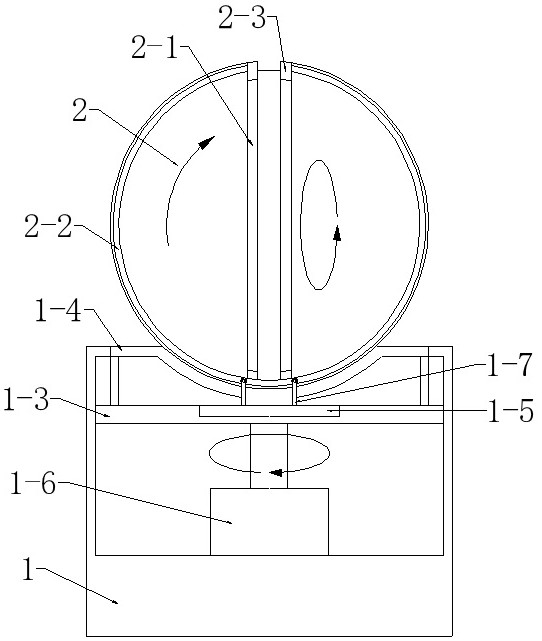
[0041] see Figure 1-Figure 17 , the present invention provides a technical solution: a drive device for adjusting the spatial position of an ultrasonic probe, the drive device includes an adjustment base 1, two sets of connecting shafts 1-9, and two sets of angle components 3, and the adjustment base 1 is rotatably mounted with a space ball 2 , the adjustment seat 1 is fixed with a group of angle components 3, two sets of connecting shafts 1-9 and two groups ...


PUM


Abstract

The invention discloses a driving device for adjusting the spatial position of an ultrasonic probe. The driving device includes an adjustment seat, two sets of connecting shafts, and two sets of angle components. The components are fixed, the two sets of connecting shafts and the two sets of angle components are spaced apart from each other, the connecting shafts and the angle components are fixed, a control handle is arranged on one set of connecting shafts, and the space ball is used to set the ultrasonic probe . The space ball is installed on the adjustment seat, and the space ball and the adjustment seat cooperate with each other to realize the angle adjustment of the ultrasonic probe in space, and the angle assembly and the coupling shaft cooperate with each other to realize the position adjustment of the adjustment seat. The space ball, the adjustment seat, and the angle assembly are three The groups cooperate with each other to realize the adjustment of the ultrasonic probe at any position in space.

Description

technical field [0001] The invention relates to the technical field of ultrasonic diagnosis, in particular to a driving device for adjusting the spatial position of an ultrasonic probe. Background technique [0002] Medical ultrasound equipment is widely used in the detection, diagnosis and treatment of diseases. In practical applications, in order to obtain a complete and clear ultrasound image in the patient's body, medical staff need to adjust the position of the ultrasound probe from time to time so that the probe Detect targets for accurate positioning and proper compression. Based on the above reasons, it is necessary for the ultrasonic probe to move horizontally, rotate around a central axis, and reciprocate around a fixed axis. [0003] The existing ultrasonic testing equipment realizes the adjustment of various angles and front and rear distances of the ultrasonic probe through the control system to control various mechanisms. Although the existing ultrasonic testi...

Claims


Application Information

Patent Timeline
Patent Type & Authority Patents(China)
IPC IPC(8): A61B8/00
CPCA61B8/44A61B8/54A61B8/4209
Inventor 王红梅钟志腾
Owner 广东恒腾科技有限公司
Why Eureka
Try Eureka