Airway open device for respiratory support in intensive care medicine

A medical and airway technology, which is applied in the field of airway unobstructed devices for respiratory support in critical care medicine, and can solve the problems of small diameter of upper suction tube and blockage inside it

Inactive Publication Date: 2021-11-09
宜宾市第一人民医院
View PDF0 Cites 0 Cited by
  • Summary
  • Abstract
  • Description
  • Claims
  • Application Information

AI Technical Summary

Problems solved by technology

[0003] Because the airways of some critically ill patients contain blood clots, and some blood clots are too large in size, and the diameter of the upper suction tube is small, resulting in larger blood clots entering the upper suction tube of the airway patency tube for respiratory support in critical care medicine. what's stuck inside

Method used


Image

  • Airway open device for respiratory support in intensive care medicine
  • Airway open device for respiratory support in intensive care medicine
  • Airway open device for respiratory support in intensive care medicine

Examples


Embodiment 1

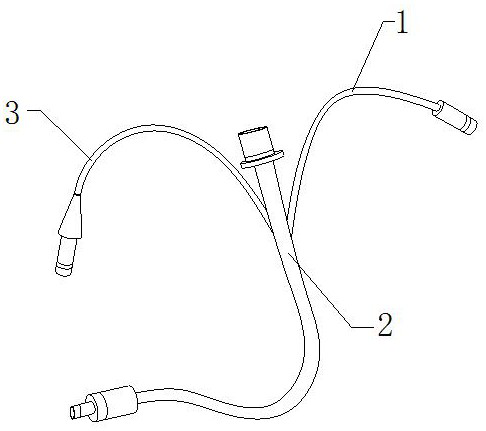
[0028] For example figure 1 -example Figure 6 Shown:

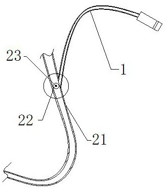
[0029] The present invention provides an airway unobstructed device for respiratory support in intensive care medicine, the structure of which includes an upper suction tube 1, an insertion tube 2, and an inflatable tube 3. The upper suction tube 1 is embedded and connected to the right side of the insertion tube 2. The insertion tube 2 is connected with the right end of the inflation tube 3; the insertion tube 2 includes a tube body 21, a rotating roller 22, and a central block 23, and the tube body 21 is connected with the right end of the inflation tube 3, and the tube body 21 The right side is embedded and connected with the upper suction tube 1 , and the rotating roller 22 is movably engaged with the middle part of the center block 23 , and the center block 23 is installed in the inner position of the tube body 21 .

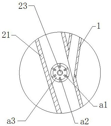
[0030] Wherein, the rotating roller 22 includes an outer slide bar a1, an elastic piece a2, and a ...

Embodiment 2

[0037] For example Figure 7 -example Figure 9 Shown:

[0038] Wherein, the upper fixing rod c1 includes a middle connecting rod c11, an outer expansion plate c12, and an elastic piece c13. The internal sliding fit of the extension rod c11, the elastic piece c13 is installed between the inner side of the outer expansion plate c12 and the middle extension rod c11, two outer expansion plates c12 are arranged, and they are evenly positioned on the left and right sides of the middle extension rod c11 The two sides are symmetrically distributed, and the outer side of the outer expansion plate c12 can always be attached to the inner wall of the object through the continuous thrust generated by the elastic piece c13 on the outer expansion plate c12.

[0039] Wherein, the connecting rod c11 includes an connecting rod d1, a vibrating block d2, and an inner connection cavity d3, the inside of the connecting rod d1 is slidingly fitted with the outer expansion plate c12, and the side of ...


PUM


Abstract

The invention discloses an airway open device for respiratory support in intensive care medicine. The airway open device structurally comprises an upper suction tube, an insertion tube and an inflation tube, wherein the upper suction tube is fixedly connected with the right side of the insertion tube in an embedded manner, the insertion tube is connected with the right end of the inflation tube, and sputum and blood clots in the airway of a critical patient are sucked through the matching of the upper suction tube and the insertion tube, so that a rotating roller can be pushed by the sputum and blood clots to rotate along a center block, outer sliding rods can extend outwards along a middle connecting ring, deformation pieces on the outer sliding rods can crush the blood clots under the cooperation of embedding grooves, and the outer sides of outer expansion plates can be tightly attached to the inner wall of the middle connecting ring through pushing force generated by elastic pieces to the outer expansion plates, so that sputum cannot be squeezed into the inner positions of the outer sliding rods and the middle connecting ring, and due to the fact that the surfaces of the outer expansion plates are smooth, the outer sliding rods can normally extend outwards.

Description

technical field [0001] The invention relates to the field of medical equipment, in particular to an airway unobstructed device for respiratory support in intensive care medicine. Background technique [0002] The airway unobstructed tube for respiratory support in intensive care is mainly used for assisted breathing for critically ill patients who are unconscious and unable to breathe spontaneously. Inhalation, so as to ensure the unobstructed airway breathing of critically ill patients, based on the above description, the inventors found that an existing airway unobstructed device for respiratory support in intensive care mainly has the following deficiencies, for example: [0003] Because the airways of some critically ill patients contain blood clots, and some blood clots are too large in size, and the diameter of the upper suction tube is small, resulting in larger blood clots entering the upper suction tube of the airway patency tube for respiratory support in critical ...

Claims


Application Information

Patent Timeline
Patent Type & Authority Applications(China)
IPC IPC(8): A61M1/00
Inventor 杨超唐勇何世会
Owner 宜宾市第一人民医院
Why Eureka
Try Eureka