
Eureka
For R&D, Eureka makes reading and utilizing patents & technical documents easy.
Eureka AIR
Designed for self-driven R&D workflows. Generate viable solutions, solve complex R&D challenges, empower your innovation with AI.

Eureka Materials
Designed for material experts only. Revolutionize your material R&D, from search, analyze, to developing new materials.

TechResearch
Generate reliable direction feasibility study reports for your R&D in just a few steps.

TechSeek
Discover and master advanced knowledge NOW. Basics, ideas, possibilities, all at once.

TechMind
As an expert in R&D Theories, TechMind can generates customized viable solutions instantly.

TechRisk
Analyze your overall solution with one click, know your potential R&D risks in advance.

TechMonitor
Get weekly tech updates, stay abreast of the latest tech innovations and key insights.
Cutting and engraving device based on paper cutting process and cutting and engraving method thereof
A craft and paper technology, applied in the field of cutting and engraving devices based on paper-cutting technology, can solve the problems of paper side-slip depiction, inaccuracy, and affecting the overall structural beauty, and achieve the effect of improving accuracy and enhancing aesthetics
- Summary
- Abstract
- Description
- Claims
- Application Information
AI Technical Summary
Problems solved by technology
Method used
Image

Examples
Embodiment 1
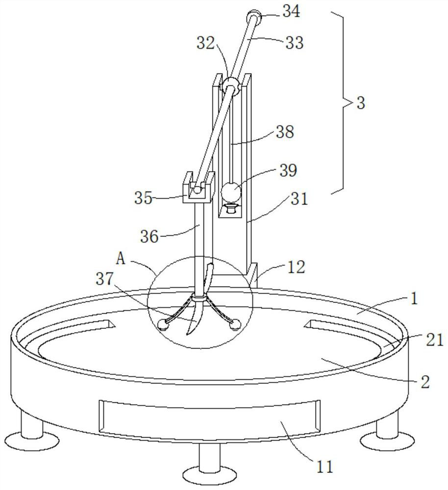
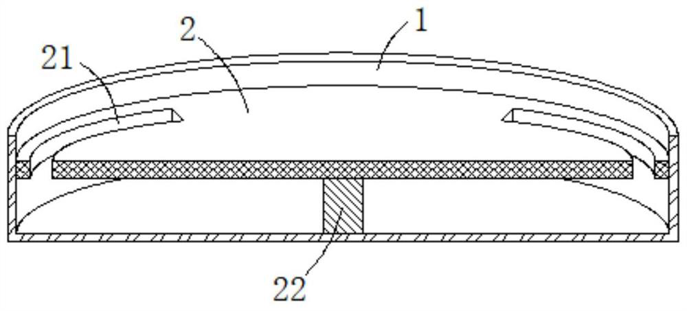
[0027] see Figure 1-4 , the present embodiment provides a cutting device and cutting method based on paper-cutting technology, a base 1, a support plate 2 and a cutting mechanism 3, the inside of the base 1 is a hollow structure without an upper cover, and the support plate 2 is rotatably mounted on the base 1 and the radial side wall of the support plate 2 is rotated and attached to the inner wall of the base 1. The bottom end of the support plate 2 is vertically fixed with a rotating rod 22. The disk 2 is rotated and installed in the base 1 through the rotating rod 22, so that the supporting disk 2 can rotate freely in the base 1.
[0028] The supporting disc 2 is used to support the paper to be cut and cut, and the supporting disc 2 rotates in the base 1 to adjust the cutting and cutting position of the supported paper, so as to perform precise cutting and cutting operations.
[0029] The radial side wall of base 1 is fixed with supporting block 12, and shearing mechanism...
Embodiment 2
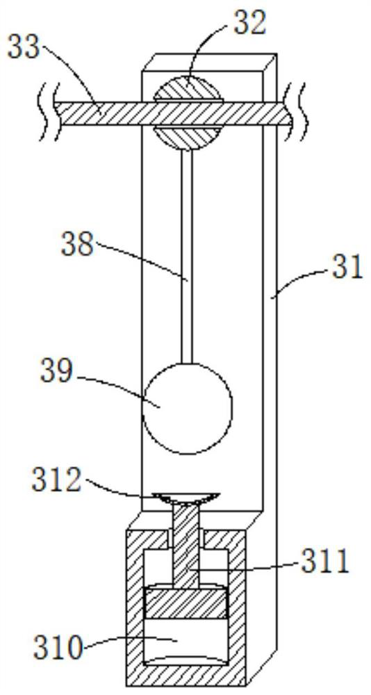
[0038] see image 3 , further improvements have been made on the basis of Example 1:
[0039] The bottom end of the spherical seat 32 is vertically fixed with a suspension rod 38, and the bottom end of the suspension rod 38 is fixedly connected with a counterweight 39. The counterweight 39 is used as a counterweight for the spherical seat 32 to prevent the spherical seat 32 from arbitrarily surrounding the pin shaft. A large swing, thereby avoiding the pull bar 36 at the tip of the cross bar 33 from swinging up and down, finally avoiding the cutting and engraving blade 37 from accidentally touching the cut and engraved paper, causing the paper to be damaged.
[0040] The inner bottom end of the rectangular notch of the column 31 is provided with an inverted T-shaped slot 310, and the interior of the inverted T-shaped slot 310 is slidably inserted with an inverted T-shaped slider 311, and the top of the inverted T-shaped slider 311 extends to the inside of the rectangular notch...
Embodiment 3
[0043] see Figure 1-4 , made further improvement on the basis of embodiment 2:
[0044] There is a height difference of not less than 10mm between the upper end surface of the support plate 2 and the top surface of the base 1, and the use of the height difference of not less than 10mm acts as a barrier, which can prevent paper debris generated after cutting from the base 1. The top edge of the is scattered on the ground and needs to be cleaned up manually.
[0045] There is a recovery hole 21 at the edge of the support plate 2 to recycle paper waste to the inside of the base 1. The shredded paper scraps generated by cutting and engraving enter the interior of the base 1 through the recovery hole 21 of the support plate 2 to realize centralized collection. The diameter of the base 1 A material guide hole 11 communicating with the inside of the base 1 is opened on the side wall, through which the scraps of paper collected inside the base 1 are conveniently poured out.
PUM
 Abstract
Description
Claims
Application Information
 - R&D Engineer
- R&D Manager
- IP Professional
- Industry Leading Data Capabilities
- Powerful AI technology
- Patent DNA Extraction
Browse by: Latest US Patents, China's latest patents, Technical Efficacy Thesaurus, Application Domain, Technology Topic, Popular Technical Reports.
© 2024 PatSnap. All rights reserved.Legal|Privacy policy|Modern Slavery Act Transparency Statement|Sitemap|About US| Contact US: help@patsnap.com