Roof exhaust system

An exhaust system and exhaust pipe technology, applied in the direction of roof, ventilation system, roof covering, etc., can solve the problems of inconvenient construction, inability to effectively prevent rainwater from entering the interior of the roof, and inability to discharge gas quickly and timely, etc., to achieve Convenient construction, prevent rainwater from entering the interior of the roof, and good exhaust effect

Pending Publication Date: 2021-11-09
JIANGSU PROVINCIAL CONSTR GRP CO LTD
View PDF8 Cites 0 Cited by
  • Summary
  • Abstract
  • Description
  • Claims
  • Application Information

AI Technical Summary

Problems solved by technology

[0003] The traditional roof exhaust system is inconvenient to construct, the gas inside the roof cannot be discharged quickly and timely, and it cannot effectively prevent rainwater from entering the roof, which affects the service life of the roof

Method used


Image

  • Roof exhaust system
  • Roof exhaust system
  • Roof exhaust system

Examples


Embodiment 1

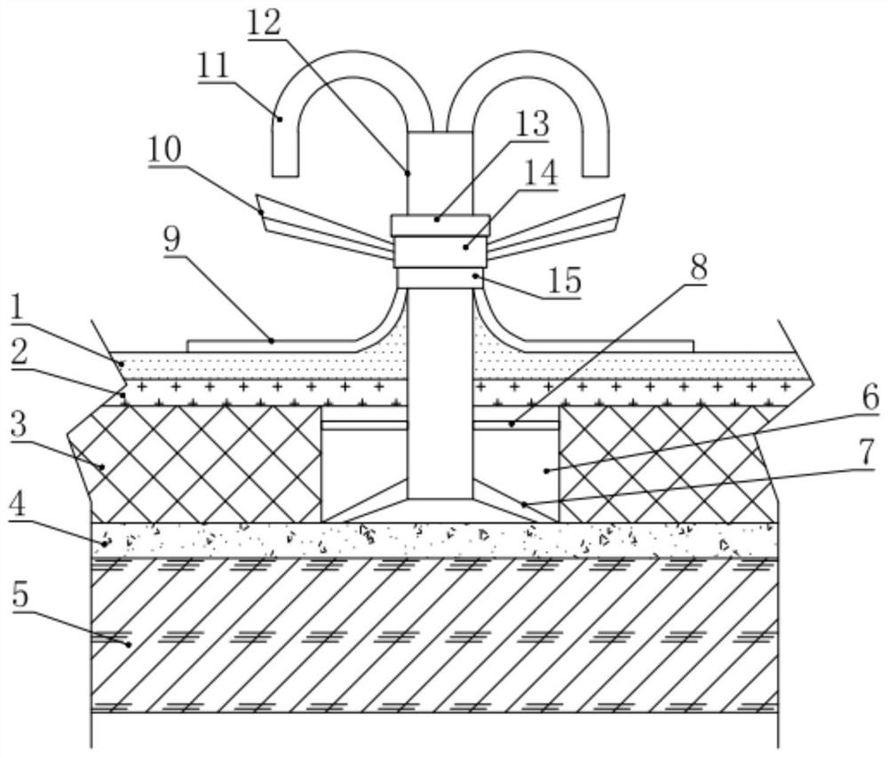
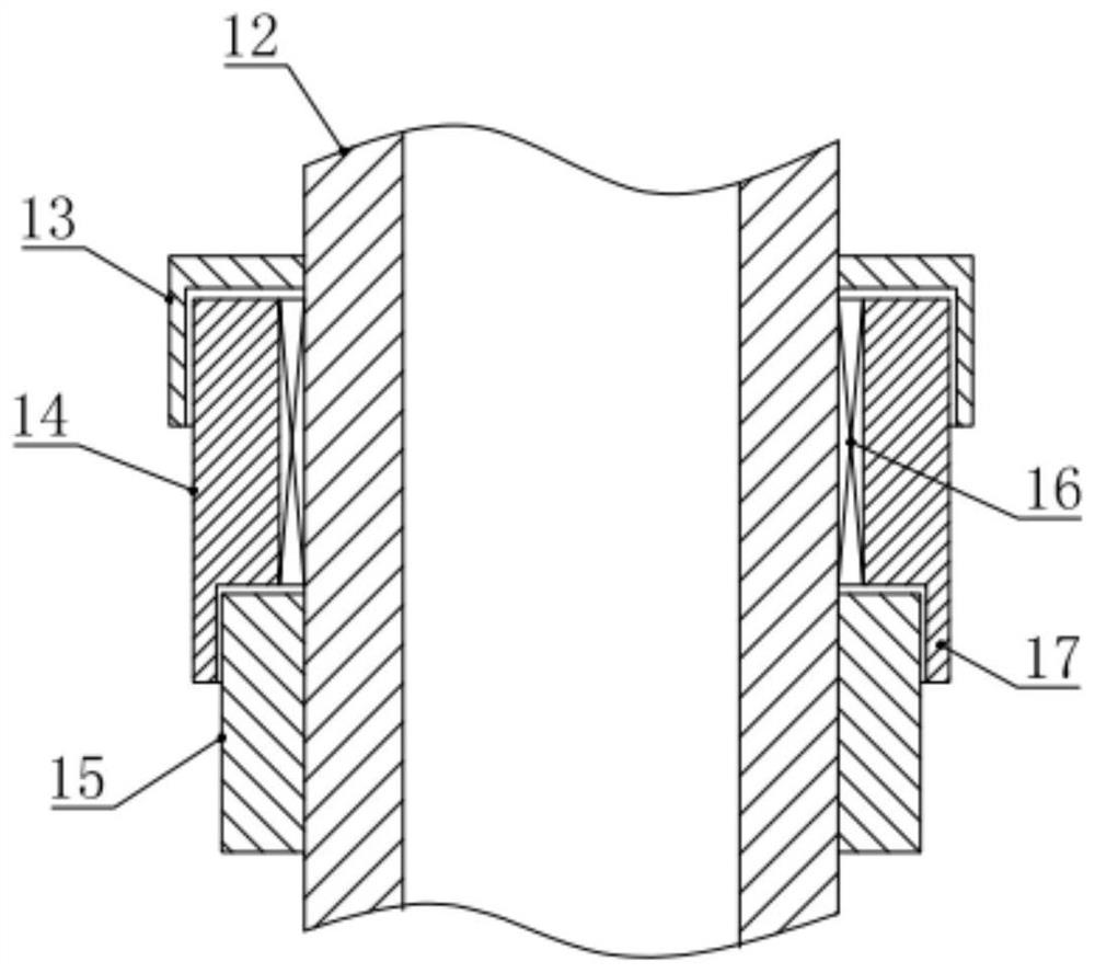
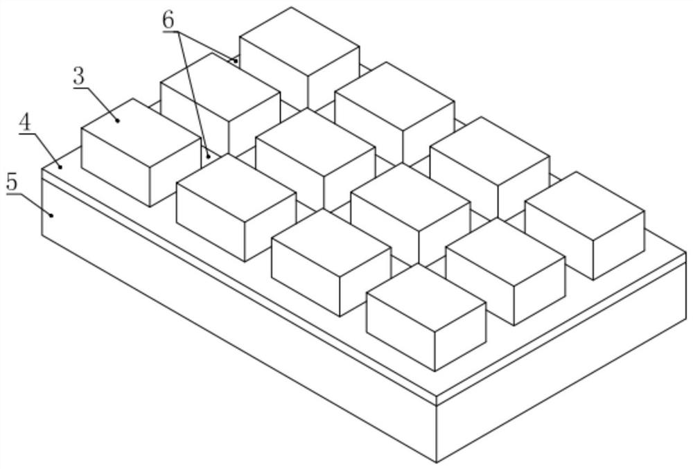
[0020] see figure 1 , 3 And 4, in an embodiment of the present invention, a roof exhaust system includes a roof, and the roof includes a waterproof layer 1, a first leveling layer 2, a thermal insulation layer 3, and a second leveling layer 4 arranged sequentially from outside to inside and the reinforced concrete structure layer 5, the thermal insulation layer 3 is provided with an exhaust channel 6 that runs vertically and horizontally, and the exhaust channel 6 is connected with a plurality of main pipes 12 protruding from the roof. A plurality of exhaust pipes 11 are arranged in the circumferential distribution of one end, and a plurality of oblique supports 7 are arranged in the circumferential distribution of the main pipe 12 close to the insulation layer 3. The main pipe 12 on the outside of the roof is installed with a unidirectional rotation device for exhausting the air. The fan blade 10 from which air is extracted from the inner cavity of the pipe 11 , and an elast...

Embodiment 2

[0024] see Figure 1-5 , the difference between this embodiment and embodiment 1 is:

[0025] In this example, if figure 1 As shown, the main pipe 12 is arranged perpendicular to the roof, and the end of the diagonal support 7 away from the main pipe 12 is fixed against the second leveling layer 4. The distance between the end of the main pipe 12 and the second leveling layer 4 is greater than 1 cm. It has a better supporting effect on the main pipe 12.

[0026] In this example, if figure 1 As shown, the main pipe 12 in the exhaust passage 6 is also circumferentially distributed with a plurality of elastic fixing parts 8 horizontally. The elastic fixing parts 8 are springs, elastic ropes or elastic rods. It is connected and fixed on the thermal insulation layer 3 , and has further elastic support effect on the main pipe 12 through the elastic fixing member 8 .

[0027] In this example, if figure 1 , 4 As shown in and 5, the exhaust pipe 11 is an inverted "U"-shaped struc...


PUM


Abstract

The invention relates to the technical field of roof moisture prevention and exhaust, in particular to a roof exhaust system. The roof exhaust system comprises a roof, wherein the roof comprises a waterproof layer, a first leveling layer, a heat preservation layer, a second leveling layer and a reinforced concrete structure layer which are sequentially arranged from outside to inside, a vertically and horizontally through exhaust channel is formed in the heat preservation layer, a plurality of main pipes extending out of the roof are arranged on the exhaust channel in a communicating mode, a plurality of exhaust pipes are arranged at the ends, away from the heat preservation layer, of the main pipes in a communicating mode in a circumferential distribution mode, a plurality of inclined supports are arranged at the ends, close to the heat preservation layer, of the main pipes in a circumferential distribution mode, fan blades used for pumping air out of inner cavities of the exhaust pipes are rotationally installed on the main pipes on the outer side of the roof in a one-way mode, and elastic waterproof cylinders are further installed on the inner sides of the ends, away from the main pipes, of the exhaust pipes. According to the roof exhaust system, construction is convenient, gas in the roof can be rapidly and timely discharged, rainwater can be effectively prevented from entering the roof, and the service life of the roof is prolonged.

Description

technical field [0001] The invention relates to the technical field of roof moisture-proof exhaust, in particular to a roof exhaust system. Background technique [0002] In roof construction, the purpose of setting roof vents is to remove the moisture in the slope-finding layer in time, so that the moisture under the waterproof layer will not evaporate due to high temperature, and the roof waterproof layer will be lifted up to damage the waterproof layer. [0003] The traditional roof exhaust system is inconvenient to construct, the gas inside the roof cannot be discharged quickly and timely, and it cannot effectively prevent rainwater from entering the roof, which affects the service life of the roof. [0004] Therefore, in view of the above current situation, it is urgent to develop a roof exhaust system to overcome the deficiencies in current practical applications. Contents of the invention [0005] The purpose of the embodiments of the present invention is to provide...

Claims


Application Information

Patent Timeline
Patent Type & Authority Applications(China)
IPC IPC(8): E04D13/17
CPCE04D13/172
Inventor 陈源源祝捷刘永林李和军邹琳何祥康张晓杰刘海刚李金柱欧阳言领王蒙张克久马星昌陈翠霞项明何金华吕波王硕柴小松赵本超杨森池崇玉王俊斌
Owner JIANGSU PROVINCIAL CONSTR GRP CO LTD
Why Eureka
Try Eureka