An electromagnetic anti-theft door

An anti-theft door and electromagnetic technology, applied in the field of anti-theft doors, can solve the problem of low anti-theft performance of electromagnetic locks, and achieve the effect of increasing anti-theft performance and improving service life

Active Publication Date: 2022-05-20
浙江星月安防科技有限公司
View PDF11 Cites 0 Cited by
  • Summary
  • Abstract
  • Description
  • Claims
  • Application Information

AI Technical Summary

Problems solved by technology

[0006] The present invention aims at providing an electromagnetic anti-theft door with significantly increased anti-theft performance, aiming at the shortcomings of the low anti-theft performance of the existing electromagnetic locks proposed in the background technology.

Method used


Image

  • An electromagnetic anti-theft door
  • An electromagnetic anti-theft door
  • An electromagnetic anti-theft door

Examples


Embodiment 1

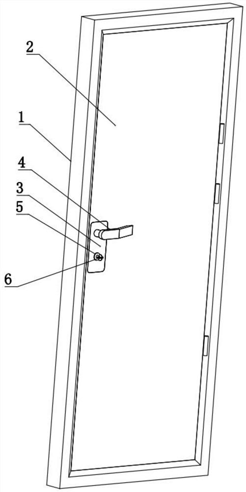
[0039] An electromagnetic anti-theft door, referring to Figure 1-Figure 6 As shown, it includes a door frame 1, a door leaf 2 hinged on the door frame 1, and an anti-theft lock on the door leaf 2. Handles 4 are arranged on both sides of the anti-theft lock. The door frame 1 is fixed on the wall, and the door frame 1 is made of stainless steel. , the door leaf 2 includes an internal fireproof door core board and a stainless steel layer wrapped outside. The thickness of the stainless steel layer is greater than 0.5cm. In this solution, the improved anti-theft lock improves the anti-theft of the entire anti-theft door by increasing the anti-theft performance of the anti-theft lock. performance.

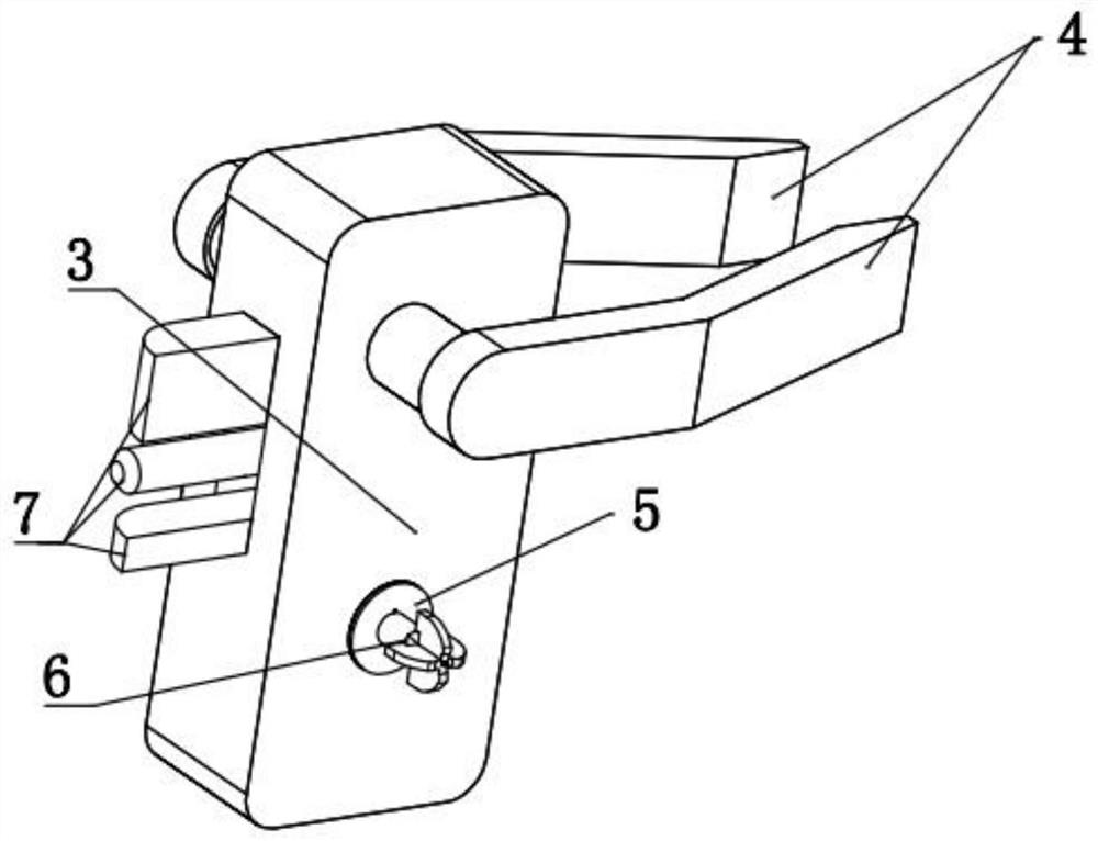
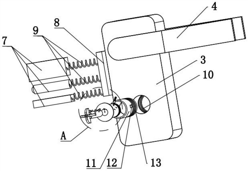
[0040] Anti-theft lock reference Figure 2-Figure 3 As shown, it includes a lock body 3 and a key 6. The lock body 3 includes at least one bolt 7 that is elastically stretchable on the side of the lock body 3 close to the door frame 1 and is inserted and locked with the door frame 1 wh...

Embodiment 2

[0053] In this embodiment, on the basis of Embodiment 1, a reinforced locking structure is added between the door leaf 2 and the door frame 1, the purpose of which is to increase the difficulty for the thief to open the door by exposure. The reinforced locking structure still firmly fixes the door leaf 2 and the door frame 1 together.

[0054] Strengthen the locking structure reference Figure 8 As shown, the plug-in lock block 28 is elastically telescopically arranged on the upper end of the door leaf 2 and / or on the side far away from the end of the deadbolt 7 and / or at the lower end. Insert or partly extend out of the slot, the expansion and contraction of the plug-in lock block 28 is controlled by the energization or de-energization of the second electromagnet 26 fixed at the bottom of the slot hole, the plug-in lock block 28 is made of iron and is inserted A second spring 27 is arranged between the lock block 28 and the second electromagnet 26, and the two ends of the se...


PUM


Abstract

The invention relates to the technical field of anti-theft doors, and discloses an electromagnetic anti-theft door, which includes a door frame, a door leaf and an anti-theft lock on the door leaf. The anti-theft lock includes a lock body and a key. The lock body includes at least one bolt and a lock fixed in the lock body. The expansion and contraction of the lock bolt is controlled by the energization or de-energization of the first electromagnet, and the energization or de-energization of the first electromagnet is controlled by the first control circuit. There is a slot recessed on the side of the lock cylinder facing the outside of the door. , a control module that can connect or disconnect the control circuit is arranged in the lock cylinder, and the control module includes N (N≥8) through slots that are recessed in the inner wall of the slot along its circumferential direction and / or axial direction. A contact module fixedly arranged at one end of the through slot away from the slot and a telescopic member elastically and telescopically arranged in each through slot, the key includes an insertion rod and a first control circuit that can be telescopically arranged on the outer ring wall of the insertion rod Connected unlocking parts, thieves can't open the security door at all by using the traditional crochet and tin foil filling unlocking methods.

Description

technical field [0001] The invention relates to the technical field of anti-theft doors, in particular to an electromagnetic anti-theft door. Background technique [0002] The anti-theft essence of the anti-theft door lies in the anti-theft lock set on it. The anti-theft locks are generally divided into A-level, B-level and C-level. It takes more than 5 minutes to open the C-level lock technology, and the C-level lock takes a long time to open, which takes several hours. Generally, thieves will give up directly when encountering the C-level lock. The essence of the C-level lock is the probability of opening. The marble structure on it is double-row 48 blades and double-type side column locking, but the manufacture of this kind of lock requires extremely high precision, and the production cost is extremely high. Therefore, the cost is also high. Based on cost considerations, people mainly use A-level locks. locks and Class B locks. [0003] The unlocking skills used by thie...

Claims


Application Information

Patent Timeline
Patent Type & Authority Patents(China)
IPC IPC(8): E05B47/00E05B15/00E05B3/00E05B1/00E06B5/11
CPCE05B47/0002E05B15/00E05B3/00E05B1/003E06B5/11
Inventor 李翠翠吕吉祥田俊佳黄向阳王川川郭延杰罗梅青陈明磊
Owner 浙江星月安防科技有限公司
Why Eureka
Try Eureka