mop bucket

A mop bucket and bucket body technology, applied in the field of mop buckets, can solve the problems of wasting space, many dead corners in the bucket, occupying a large space, etc., and achieve the effects of not easy to damage, scientific and reasonable design, and small space occupation

Inactive Publication Date: 2019-08-23
金广成
View PDF11 Cites 0 Cited by
  • Summary
  • Abstract
  • Description
  • Claims
  • Application Information

AI Technical Summary

Problems solved by technology

[0008] In order to overcome the defects that the existing mop bucket takes up a lot of space, is easy to be damaged, has many dead spots in the bucket, wastes water and space, the purpose of the present invention is to provide a convenient two-in-one mop bucket that integrates cleaning and dehydration functions

Method used


Image

  • mop bucket
  • mop bucket
  • mop bucket

Examples


Embodiment 1

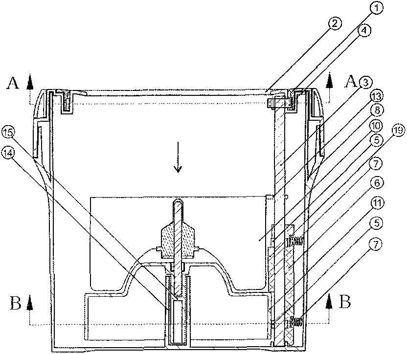
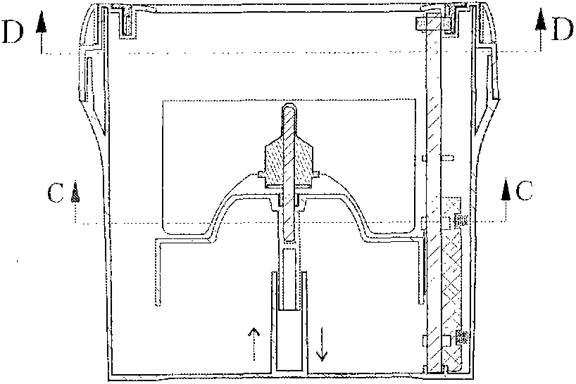
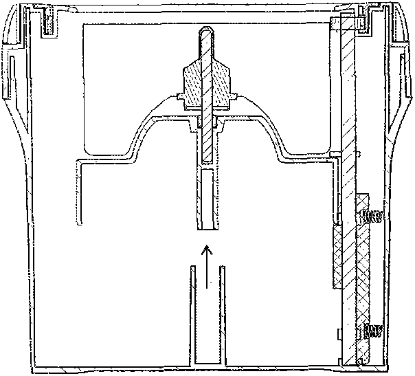
[0043] refer to Figure 1-7To describe one of the preferred solutions of the present invention, a mop bucket includes a bucket body 8, a dehydration basket 10, and a top cover 2. The dehydration basket is located in the bucket body, and the top cover is located on the top edge of the bucket body; Limiting system 16, float 11, the float is located under the dehydration basket 10; the positioning system for lateral movement includes a vertical shaft 3, an eccentric wheel 5, and a support slider 6 for limiting movement in the lateral direction; There is an eccentric wheel chute 17 and a return spring 7 on the position support slider 6; the vertical shaft 3 is clamped and fixed vertically in the barrel, the eccentric wheel 5 passes through the vertical shaft 3 and is located in the eccentric wheel chute 17, and the return spring 7 is located in the horizontal direction Swimming is fixed on the position-limiting support slide block 6, and lateral movement is fixed between the posit...

Embodiment 2

[0046] Such as Figure 8 As shown, the positioning insert 14 and the positioning clip 15 are different from those in Embodiment 1, and the rest are as shown in Embodiment 1.

Embodiment 3

[0048] Such as Figure 9 As shown, the buoy is a fully enclosed hollow structure.


PUM


Abstract

The invention relates to a mop barrel, belongs to the field of daily necessities, and overcomes the defects that an existing mop barrel is large in space occupation, easy to damage and wasteful in water and space, and more dead corners exist inside the barrel. The two-in-one mop barrel which is convenient to use and integrated with functions of cleaning and dewatering comprises a barrel body, a dewatering basket and a top cover, the dewatering basket is located in the barrel body, and the top cover is located at the side edge at the top end of the barrel body; the mop barrel further comprises a horizontal-movement positioning and limiting system and a buoy which is located under the dewatering basket; the horizontal-movement positioning and limiting system comprises a vertical shaft, an eccentric wheel and a horizontal-movement positioning and limiting supporting slider; the horizontal-movement positioning and limiting supporting slider is provided with an eccentric wheel sliding groove and reset springs; the vertical shaft is located in the barrel body, the eccentric wheel penetrates the vertical shaft to be located in the eccentric wheel sliding groove, and the reset springs are located on the horizontal-movement positioning and limiting supporting slider and between the horizontal-movement positioning and limiting supporting slider and the barrel body. The mop barrel is scientific and reasonable in design, different from the design principle of the existing rotating mop barrel, simple, less prone to damage, small in space occupation, energy saving, water saving and suitable for popularization and application.

Description

[0001] Technical field: [0002] The invention relates to a mop bucket, which belongs to the field of daily necessities. [0003] Background technique: [0004] The mop is the most commonly used cleaning tool for cleaning the floor. Scrubbing the floor with a clean and moist mop is the most environmentally friendly and convenient way to clean the floor. Excessive use of the mop often requires water to clean. In order to clean the mop more conveniently in the prior art, a mop bucket, the mop bucket often adopts a structure with a cleaning bucket on one side and a dehydration basket on the other, and a foot pedal linkage with the dehydration basket for dehydration, but such a structure takes up more space. In addition, the user needs a foot Standing and stepping on the other foot to dehydrate, often fall down due to slippery or uneven force, resulting in unstable standing, poor safety, so the mop is designed with its own rotating parts, and the dehydration basket does not have a ...

Claims


Application Information

Patent Timeline
Patent Type & Authority Patents(China)
IPC IPC(8): A47L13/58
Inventor 金广成
Owner 金广成
Why Eureka
Try Eureka