Air duct structure, air conditioner and air conditioner control method

A control method and technology for air conditioners, applied in heating and ventilation control systems, air conditioning systems, heating methods, etc., can solve the problems of low reliability of air conditioners, and achieve the effects of low reliability and short waiting time.

Inactive Publication Date: 2021-11-09
GREE ELECTRIC APPLIANCES INC
View PDF6 Cites 1 Cited by
  • Summary
  • Abstract
  • Description
  • Claims
  • Application Information

AI Technical Summary

Problems solved by technology

[0004] The main purpose of the present invention is to provide an air duct structure, an air conditioner and an air conditioner control method to solve the problem of low reliability of the air conditioner in the prior art

Method used


Image

  • Air duct structure, air conditioner and air conditioner control method
  • Air duct structure, air conditioner and air conditioner control method
  • Air duct structure, air conditioner and air conditioner control method

Examples


Embodiment Construction

[0038] It should be noted that, in the case of no conflict, the embodiments in the present application and the features in the embodiments can be combined with each other. The present invention will be described in detail below with reference to the accompanying drawings and examples.

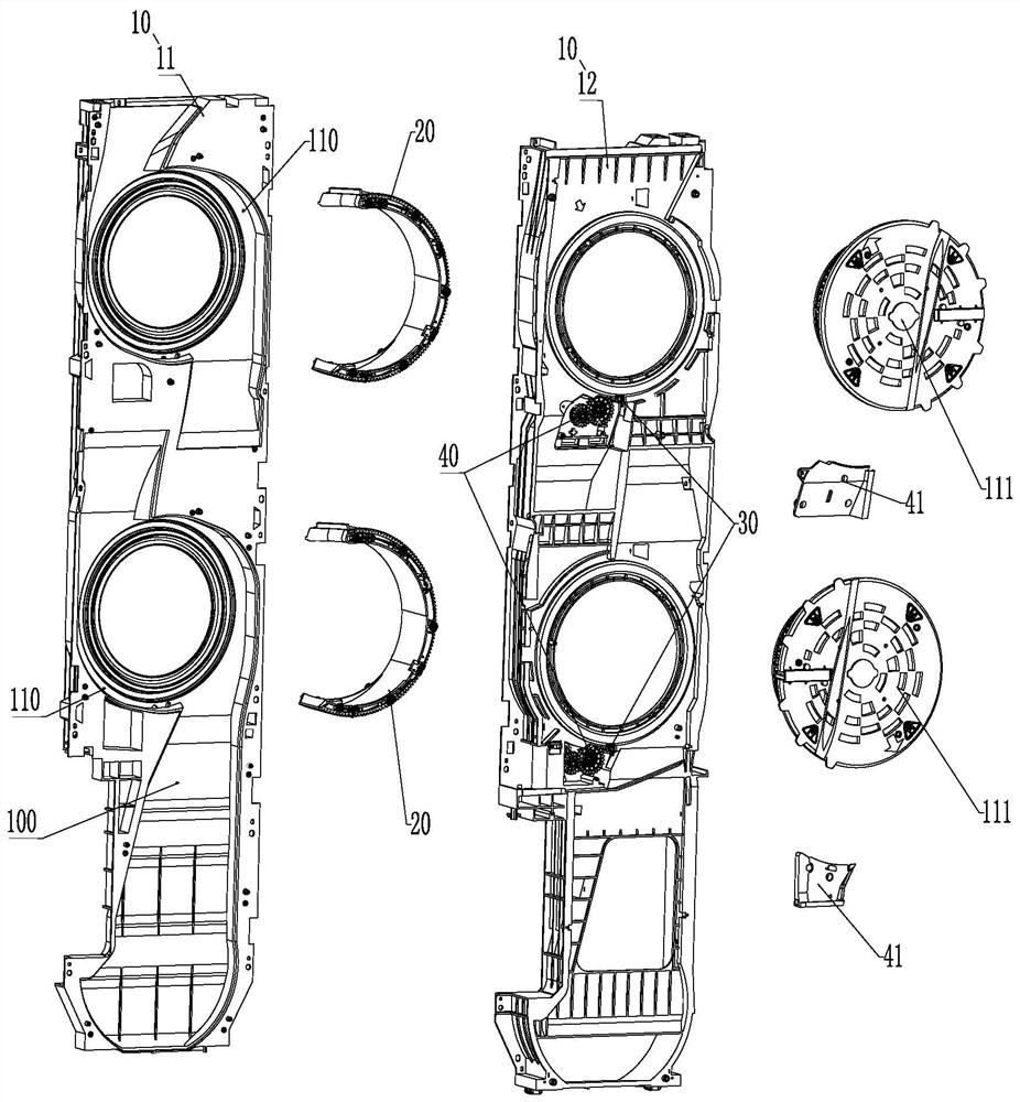
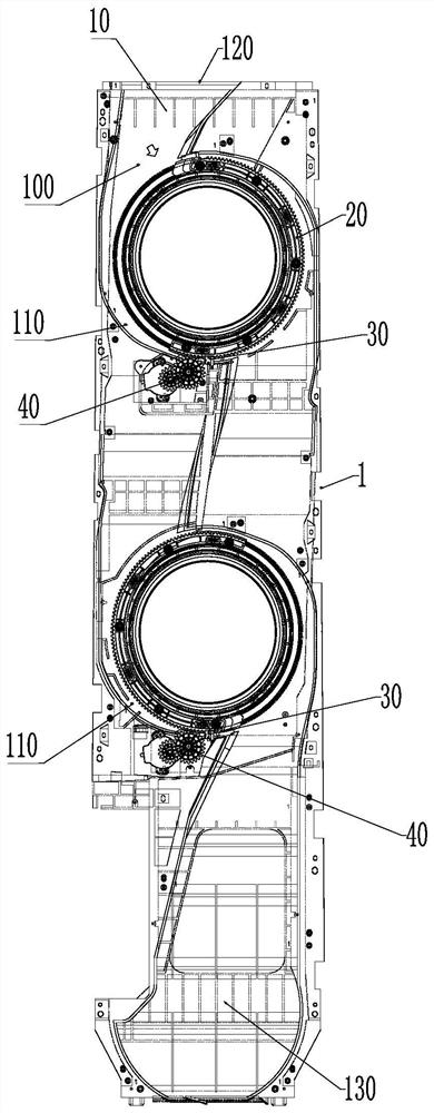
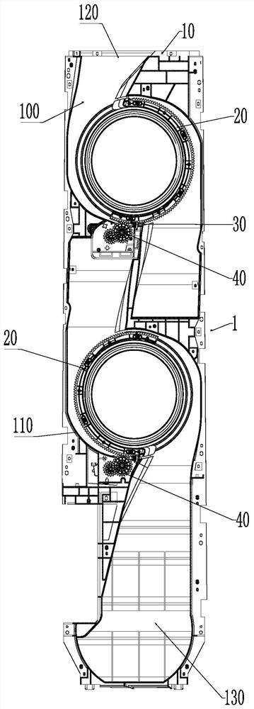
[0039] Please refer to Figure 1 to Figure 14 , the present invention provides an air duct structure, including: a volute assembly 10, the volute assembly 10 has an air duct 100, and a fan installation cavity 110 is arranged in the air duct 100; a volute tongue assembly 20, and the volute tongue assembly 20 is arranged on the Inside the installation cavity 110 ; the micro switch 30 , the micro switch 30 is arranged on the volute assembly 10 or the volute tongue assembly 20 , so that the volute tongue assembly 20 is limited to an initial position by the micro switch 30 .

[0040] The air duct structure provided by the present invention includes a volute assembly 10 and a volute tongue assembly ...


PUM


Abstract

The invention provides an air duct structure, an air conditioner and an air conditioner control method. The air duct structure comprises a volute assembly, a volute tongue assembly and a microswitch, wherein the volute assembly is provided with an air duct, and the air duct is internally provided with a fan mounting cavity; the volute tongue assembly is arranged in the fan mounting cavity; and the microswitch is arranged on the volute assembly or the volute tongue assembly, so that the volute tongue assembly is limited at the initial position through the microswitch. The problem that in the prior art, an air conditioner is low in use reliability is solved.

Description

technical field [0001] The invention relates to the field of air conditioners, in particular to an air duct structure, an air conditioner and an air conditioner control method. Background technique [0002] The upper and lower air outlet cabinets can realize carpet-type heating and shower-type cooling, with good comfort and great development prospects. The rotating volute tongue air duct part adopts the rotating volute tongue mode: when cooling, the rotating volute tongue is in the upward air outlet state; when heating, the rotating volute tongue rotates to the downward air outlet state. This implementation method is novel and highly feasible. [0003] However, due to the repeated rotation of the rotating volute tongue, there will be hidden dangers such as motion jamming and abnormal motion of the rotating volute tongue, which will affect the reliability of the whole machine. Contents of the invention [0004] The main purpose of the present invention is to provide an air...

Claims


Application Information

Patent Timeline
Patent Type & Authority Applications(China)
IPC IPC(8): F24F1/0014F24F1/0033F24F11/64F24F11/67F24F11/79F24F11/89
CPCF24F1/0014F24F1/0033F24F11/64F24F11/67F24F11/79F24F11/89
Inventor 陈红光柳烨潘龙腾张瀚中何振健王宏望
Owner GREE ELECTRIC APPLIANCES INC
Why Eureka
Try Eureka