Aviation steel cable tension accurate measurement device
What is AI technical title?
AI technical title is built by Patsnap AI team. It summarizes the technical point description of the patent document.
A technology of precise measurement and wire rope, applied in the direction of tension measurement, etc., can solve the problem of insufficient accuracy of wire tension measurement, and achieve the effect of reducing measurement workload, high measurement repeatability, and easy realization
Active Publication Date: 2021-11-09
西安华羽通盛科技有限责任公司
View PDF14 Cites 0 Cited by
Summary
Abstract
Description
Claims
Application Information
AI Technical Summary
This helps you quickly interpret patents by identifying the three key elements:
Problems solved by technology
Method used
Benefits of technology
Problems solved by technology
Solved the technical problem of insufficient accuracy of cable tension measurement
Method used
Image
Click on the blue label to locate the original text in one second.
Reading with bidirectional positioning of images and text.
Examples
Embodiment 1
[0059] Such as Figure 1-Figure 4 Shown:
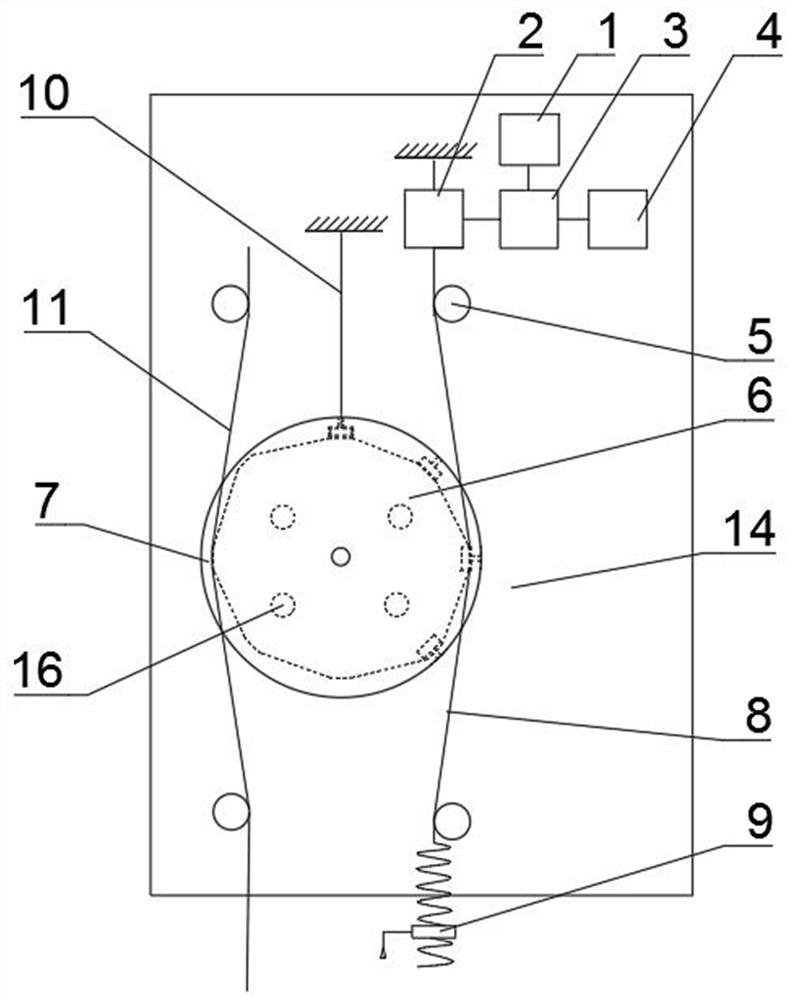
[0060] The present invention provides an accurate measurement device for aviation cable tension, which includes a pulley 5, an upper block 6, a lower block 7, a force-measuring cable 8, a connecting plate 10, a steel cable 11 to be tested and a bottom plate 14, wherein:
[0061] The upper block 6 is installed and fixed above the lower block 7;
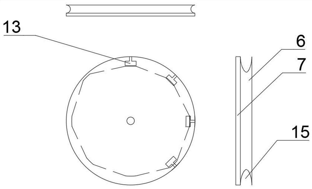
[0062] The upper pad 6 is a circular plate structure, and the side of the pad 6 is provided with a side groove 15;
[0063] The lower pad 7 is a circular plate-shaped structure, and the lower pad 7 is provided with a plurality of T-shaped grooves 13;
[0064] The two centers of the upper pad 6 and the lower pad 7 coincide, and a through hole is provided at the center of the circle;
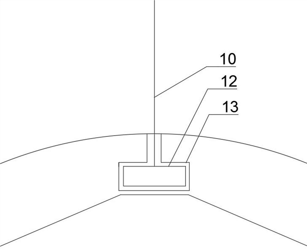
[0065] One end of the connecting plate 10 is fixed on the bottom plate 14, and the other end is provided with a T-shaped piece 12;
[0066] The T-shaped piece 12 is embedded in the T-shaped groove 13 and match...
Embodiment 2
[0086] The present invention provides an accurate measurement device for aviation cable tension, which includes a pulley 5, an upper block 6, a lower block 7, a force-measuring cable 8, a connecting plate 10, a steel cable 11 to be tested and a bottom plate 14, wherein:
[0087] The upper block 6 is installed and fixed above the lower block 7;
[0088] The upper pad 6 is a circular plate-shaped structure, and the side of the pad 6 is provided with a side groove 15, and the depth of the side groove 15 is uneven, and its depth value is about that of the upper pad 6. Symmetrical to the center of the circle;
[0089] The lower pad 7 is a circular plate-shaped structure, and the lower pad 7 is provided with a plurality of T-shaped grooves 13;
[0090] The two centers of the upper pad 6 and the lower pad 7 coincide, and a through hole is provided at the center of the circle;
[0091] One end of the connecting plate 10 is fixed on the bottom plate 14, and the other end is provided ...
PUM
Abstract
The invention provides an aviation steel cable tension accurate measurement device, and relates to the technical field of tension measurement equipment. The aviation steel cable tension accurate measurement device comprises a pulley (5), an upper cushion block (6), a lower cushion block (7), a force measuring steel cable (8), a connecting plate (10), a measured steel cable (11) and a bottom plate (14), a side groove (15) is formed in the upper cushion block (6), a plurality of T-shaped grooves (13) are formed in the lower cushion block (7), the circle centers of the side groove (15) and the T-shaped grooves (13) coincide, and a through hole is formed in the circle center; one end of the connecting plate (10) is fixed on the bottom plate (14), and the other end of the connecting plate (10) is provided with a T-shaped piece (12); the number of the pulleys (5) is four, the pulleys (5) are arranged in a rectangular shape, the center of the rectangle is provided with a red dot fixed on the bottom plate (14), one end of the force measuring steel cable (8) is connected with the sensor (2), and the other end of the force measuring steel cable (8) is connected with the lead screw (9). The technical problem that the steel cable tension measurement accuracy is insufficient is solved.
Description
technical field [0001] The invention relates to the technical field of tension measuring equipment, in particular to an accurate tension measuring device for aviation steel cables. Background technique [0002] Cable transmission is widely used in aircraft, among which the aircraft control system uses more cable transmission, generally aileron control, elevator control, rudder control, rudder surface lock control, rudder surface trim control, throttle control, etc., in use When cable transmission, generally pay attention to the following four points: First, the steel cable must meet the pre-tightening force requirements after assembly. If the steel cable pre-tightening force is insufficient and the steel cable is loose, it will slide relative to the pulley, affecting The accuracy of the operation is also easy to cause the wear of the pulley; if the pre-tightening force is too large, the steel cable will bear an excessive load, and the friction force between the steel cable a...
Claims
Application Information
Patent Timeline
Application Date:The date an application was filed.
Publication Date:The date a patent or application was officially published.
First Publication Date:The earliest publication date of a patent with the same application number.
Issue Date:Publication date of the patent grant document.
PCT Entry Date:The Entry date of PCT National Phase.
Estimated Expiry Date:The statutory expiry date of a patent right according to the Patent Law, and it is the longest term of protection that the patent right can achieve without the termination of the patent right due to other reasons(Term extension factor has been taken into account ).
Invalid Date:Actual expiry date is based on effective date or publication date of legal transaction data of invalid patent.

