Supercharge Your Innovation With Domain-Expert AI Agents!

A non-contact stratified flow field measurement method

A measurement method and non-contact technology, applied in fluid velocity measurement, measurement device, velocity/acceleration/impact measurement, etc., can solve the problem that particle image velocity measurement cannot achieve multi-layer flow field measurement, and achieve high measurement efficiency and simple operation. , the result is accurate

Active Publication Date: 2022-01-07
NANJING HYDRAULIC RES INST
View PDF7 Cites 0 Cited by
  • Summary
  • Abstract
  • Description
  • Claims
  • Application Information

AI Technical Summary

Problems solved by technology

[0006] The purpose of the present invention is to provide a non-contact layered flow field measurement method, which aims to solve the problem that the particle image velocity measurement in the existing non-contact flow field measurement method cannot realize the measurement of the multi-layer flow field along the shooting direction

Method used


Image

  • A non-contact stratified flow field measurement method
  • A non-contact stratified flow field measurement method
  • A non-contact stratified flow field measurement method

Examples


Embodiment 1

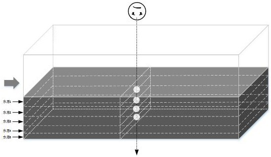
[0032] The invention discloses a method for measuring a non-contact stratified flow field. The method is used for measuring the flow velocity distribution of a water tank along the water depth direction. The method specifically includes the following steps:

[0033] (1) Set the water flow of the tank as several water layers along the water depth direction, and the contact surface between adjacent water layers is the interface; place the tracer particles one by one on each interface, and fix them on the tank in the vertical and horizontal directions A camera, through which calibration images of tracer particles on various surfaces are taken

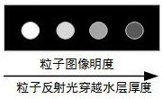
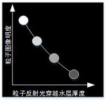
[0034] Determine the relationship between particle brightness and position: under the same conditions, the farther the object reflects light from the camera, the lower the brightness in the image; the farther the propagation distance in water, the lower the brightness in the image. According to the positional relationship, the step (1) is ...

Embodiment 2

[0050] Measure the flow velocity distribution in the cross-section direction of the tank (along the shooting direction), and the camera is placed on the side of the tank to shoot. The side wall of the tank near the camera is made of transparent material. In order to enhance the contrast between the particles and the shooting background, the side wall of the tank far away from the camera is made of low-light materials such as dark gray or black.

[0051] Subsequent steps are the same as in Embodiment 1.

Embodiment 3

[0053] To enhance the particle image contrast, the tracer particles are coated with a waterproof fluorescent material.


PUM


Abstract

The invention discloses a method for measuring a non-contact layered flow field, which comprises the steps of: taking a calibration image of tracer particles on various interfaces through a camera; , make a calibration curve; distinguish each water layer according to the particle brightness; throw tracer particles in the upstream water, acquire and process the image, extract the image of the image IMG1 in each water layer according to the above brightness; obtain the image at T+Δt time, Process the image, extract the images of the image IMG2 in each water layer according to the brightness; calculate the image extracted from the image IMG1 and the image extracted from the image IMG2 to obtain the flow velocity of other tracer particles in the water layer, and calculate the ergodic displacement process to obtain the velocity of tracer particles in other water layers. The invention realizes the synchronous measurement of the flow velocity of multiple water layers and multiple measuring points, and has simple operation, high measurement efficiency and accurate results.

Description

technical field [0001] The invention belongs to the field of water conservancy engineering, in particular to a method for measuring a non-contact stratified flow field. Background technique [0002] The flow velocity of water is the most basic physical quantity of the flow field. The understanding of the flow characteristics largely depends on the acquisition of the velocity field. The measurement of the flow velocity can provide important experimental data for the study of fluid dynamics. At present, flow field velocity measurement is mainly divided into two methods: contact and non-contact. [0003] Contact measurement mainly includes mechanical method, Pitot tube method and Doppler method, and non-contact measurement mainly includes particle image method. Commonly used instruments and equipment in practical applications include: propeller flow meter, pitot tube, differential pressure sensor, ultrasonic / laser Doppler flow meter, etc. The above instruments are all direct c...

Claims


Application Information

Patent Timeline
Patent Type & Authority Patents(China)
IPC IPC(8): G01M10/00G01P5/20
CPCG01M10/00G01P5/20
Inventor 阮仕平徐世凯李云徐业青丁文浩赵金箫王勇董波仲跻文陆德中马新红高德申张良张琦张睿王文康
Owner NANJING HYDRAULIC RES INST
Features
  • R&D
  • Intellectual Property
  • Life Sciences
  • Materials
  • Tech Scout
  • Unparalleled Data Quality
  • Higher Quality Content
  • 60% Fewer Hallucinations
Learn More