
Low voltage boosting device for rural power grid tail end

A low-voltage, electric device technology, applied in the field of low-voltage lifting devices, can solve difficult cleaning, high labor intensity, frequent problems, etc., to reduce the risk of misjudgment and damage, reduce the impact of magnetic field mutations, and reduce the rate of magnetic field mutations Effect

Pending Publication Date: 2021-11-09
普泰克电力有限公司
View PDF0 Cites 0 Cited by
  • Summary
  • Abstract
  • Description
  • Claims
  • Application Information

AI Technical Summary

Problems solved by technology

[0004] Due to the existence of a large number of dust particles in the air, after long-term use, the dust is deposited in the voltage booster. These dusts contain metal and magnetic particles, which will be adsorbed on the voltage booster after a long period of magnetization. It is difficult to clean and the dust has accumulated too much. Most of them will have a serious impact on the internal power devices, and serious accidents such as short circuits will be caused after excessive adsorption of metal particles. The existing treatment method is to manually clean the inside of the device by people on a regular basis. The interval between the two cleanings should not be too long, otherwise, after the metal particles are magnetized, it will be more difficult to clean. Therefore, the cleaning of the low-voltage lifting device is relatively frequent at present. Manual cleaning brings great labor intensity and there is a certain risk of electric shock. , we propose a low-voltage lifting device for the end of the rural power grid

Method used


Image

  • Low voltage boosting device for rural power grid tail end
  • Low voltage boosting device for rural power grid tail end
  • Low voltage boosting device for rural power grid tail end

Examples


Embodiment Construction

[0028] The following will clearly and completely describe the technical solutions in the embodiments of the present invention with reference to the accompanying drawings in the embodiments of the present invention. Obviously, the described embodiments are only some, not all, embodiments of the present invention. Based on the embodiments of the present invention, all other embodiments obtained by persons of ordinary skill in the art without making creative efforts belong to the protection scope of the present invention.

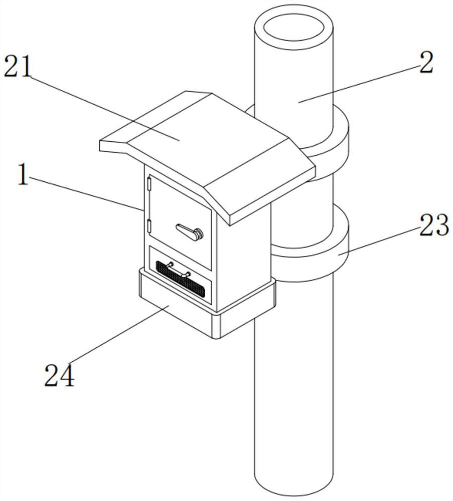
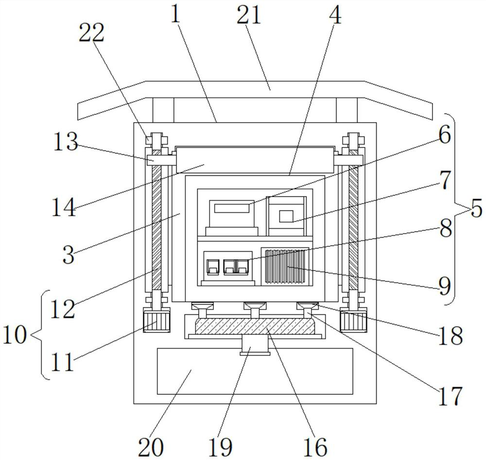
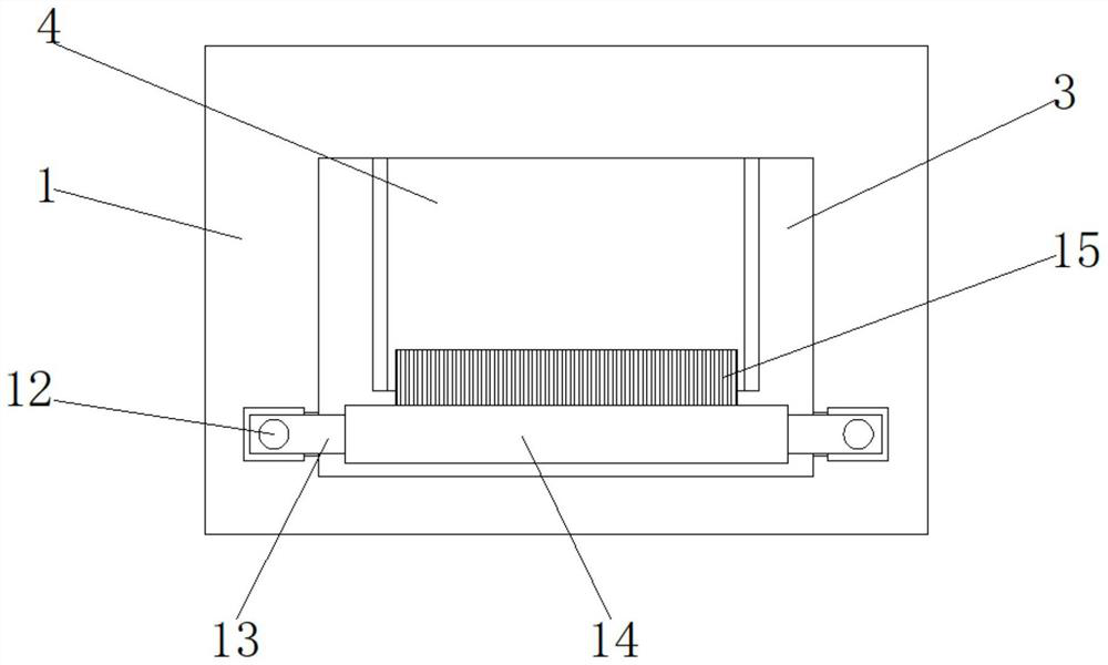
[0029] see Figure 1-Figure 4 , the present invention provides a low-voltage lifting device for the end of the rural power grid, including a box body 1 and a protective device 2, a cavity 3 is opened inside the box body 1, and an installation frame 4 is fixedly installed inside the cavity 3, and the installation The inside of the frame 4 is fixedly equipped with a power device 5, and the left and right sides of the inner wall of the box body 1 are fixedly equi...


PUM


Abstract

The invention discloses a low voltage boosting device for a rural power grid tail end. The low voltage boosting device for the rural power grid tail end comprises a box body and a protection device arranged at one side of the box body, the protection device is used for forming a magnetic field at the periphery of the box body, and a cavity is formed in the box body. A mounting frame is fixedly mounted in the cavity, an electric power device is fixedly mounted in the mounting frame, and driving mechanisms are fixedly mounted at the left side and the right side of the inner wall of the box body; sliding blocks are in threaded connection with the outer surfaces of the two driving mechanisms, a moving plate is fixedly mounted between the two sliding blocks, a brush is fixedly installed on the rear side wall of the moving plate, and a dust removal mechanism is fixedly installed at the bottom of the cavity. Dust can be discharged into a dust collecting groove through a dust discharging pipe, and convenience is provided for the subsequent cleaning work of workers.

Description

technical field [0001] The invention belongs to the technical field of low-voltage lifting devices, and in particular relates to a low-voltage lifting device used at the end of a rural power grid. Background technique [0002] At present, the voltage of the rural power grid is unstable, and the voltage is often too low, which makes many high-power household appliances unable to start and use normally. The voltage of the transformer is normal when it is unloaded, but during the peak period of power consumption, the voltage at the output terminal of the transformer drops to 225V at the lowest, and the terminal voltage of the user is lower than 200V, which has a certain impact on production and life. Generally, a low-voltage booster device is installed to solve this problem. [0003] The current voltage boosting device is usually used in conjunction with transformers and other devices, and its installation is usually located not far from the transformer, and there is usually a ...

Claims


Application Information

Patent Timeline
IPC IPC(8): H02B1/28H02B1/46B08B1/00H02J13/00H05K9/00
CPCH02B1/28H02B1/46H02J13/00022H05K9/0007B08B1/12Y02E60/00Y02B70/30Y02B90/20Y04S20/242Y04S40/126
Inventor 易刚刘念陈恳
Owner 普泰克电力有限公司
Learn More